
Creating Patterns with PropCad Premium


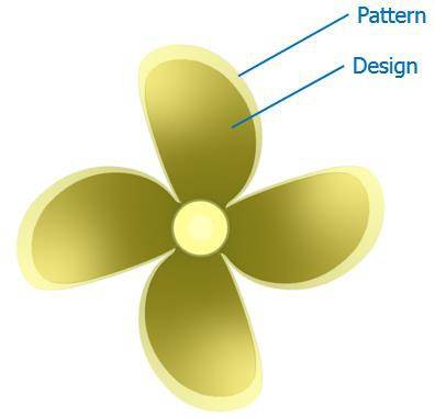
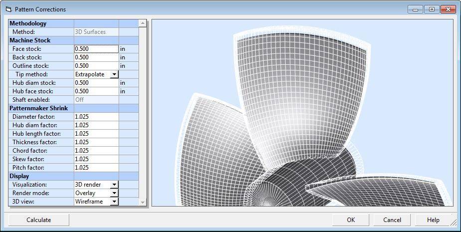
 Pattern Corrections is used to expand and thicken propeller designs to create machining models and casting patterns. Individual control is provided for separate blade parameters. (Image: HydroComp)
 (Image: HydroComp)
 (Image: HydroComp)
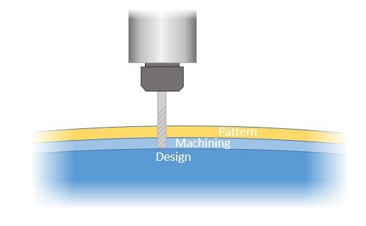
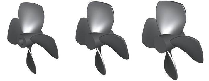 Design geometry, machining geometry, pattern geometry (Image: HydroComp)


The new Pattern Corrections utility allows users to quickly create machining models, casting patterns, and molds DIRECTLY from PropCad
HydroComp announced its PropCad software for the geometric modeling of marine propellers has receieved an upgrade. Now, PropCad Premium introduces another powerful feature, the Pattern Corrections tool.
HydroComp’s Pattern Corrections tool reduces manipulation of the propeller design within a 3D CAD tool. Pattern Corrections allows users to directly specify machine stock and shrinkage to create machining models, casting patterns and mold geometries. An advantage is that these corrections are applied directly to the propeller parameters, allowing calculation and visualization of sections, blade parameters and radial distributions. The Pattern Corrections utility also allows users to document these corrections and saves them to the original design file. Consequently, adjustments to the pattern can be made rapidly and easily.
When using the Pattern Corrections utility, it is important that the user has an understanding of the manufacturing operation. There are three geometry models that are commonly used to produce a propeller:
- Design geometry – This is the geometry of the final, finished propeller. This model can be used to produce the "drive surfaces" for CNC machining.
- Machining geometry – This is the geometry of the propeller that includes extra material for machining via milling or grinding operations. This model is often used as the "stock model" for CNC machining operations performed on propeller castings.
- Pattern geometry – This geometry (also known as a casting geometry) is used to create the propeller mold. It includes the extra material for machining, and also includes "shrinkage factors" that correlate to the reduction in size that occurs when the molten material used to pour the propeller cools and solidifies.
The user is required to specify all machining and shrinkage values for the Pattern Corrections utility. This should be done in consultation with the foundry or machining center that is manufacturing the propeller.
The Pattern Corrections provides a clear, easy-to-use interface. The machine stock and patternmakers shrink corrections have individual control of the different blade parameters to provide the necessary flexibility. The visualization below shows a sample of a Kaplan-style blade, with the corrected geometry as a (wireframe) over the design geometry (solid).
Once the corrections have been specified, the derived geometry is displayed in PropCad where the user has full control over the distributions, offsets, and parameters. Additionally, 3D models, 2D drawings, and offset reports can be generated for the new geometries.