
Moving Ahead Powerfully


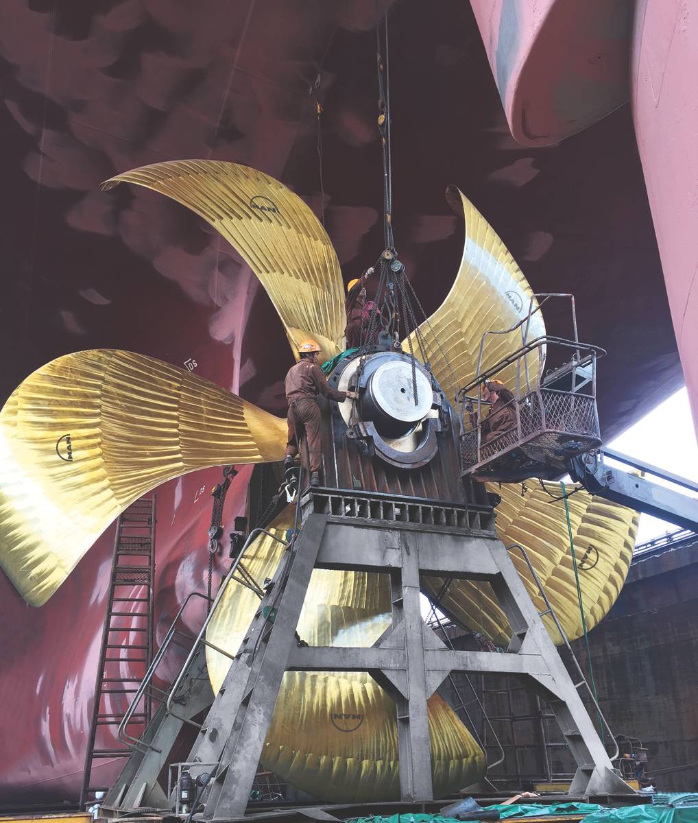
 (Photo: MAN Diesel & Turbo)
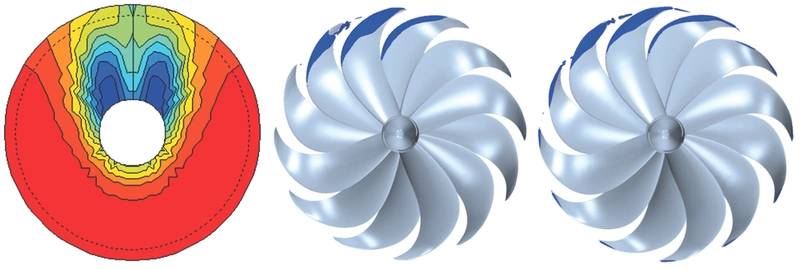 Figure 1: In the non-homogeneous wake flow, sheet cavitation occurs on the leading edge of the propeller in the upper region due to increased angle of attack and low hydrostatic pressure. This becomes detached (cloud cavitation) or becomes tip vortex cavitation. (Image: MAN Diesel & Turbo)
 Figure 2: Sheet cavitation is detached due to turbulent flows and becomes cloud cavitation (Image: MAN Diesel & Turbo)
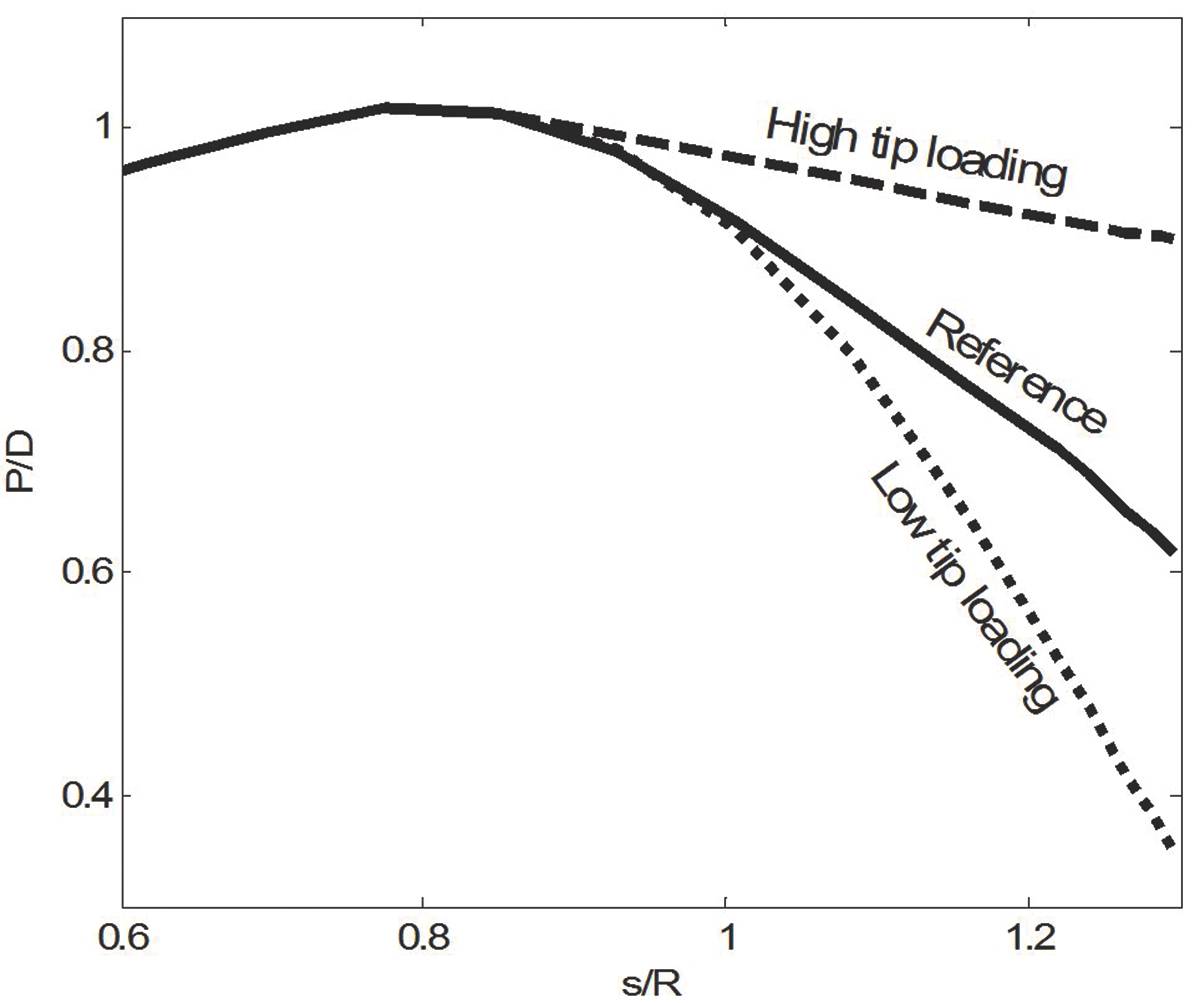
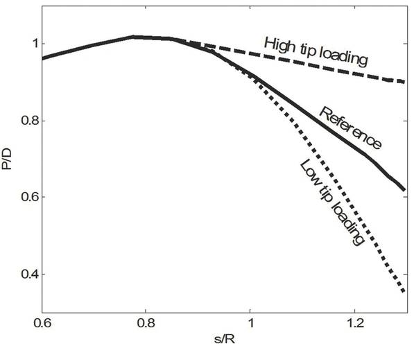 Figure 3: Pitch distribution P/D as a function of the relative mid-chord length s/R (Image: MAN Diesel & Turbo)
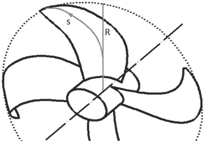
 Figure 4: Computational space for the propeller simulation (Image: MAN Diesel & Turbo)
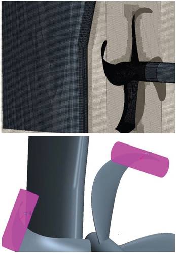 Figure 5: Grid refinements are used on the propeller surface and the blade tips to achieve better resolution. (Image: MAN Diesel & Turbo)
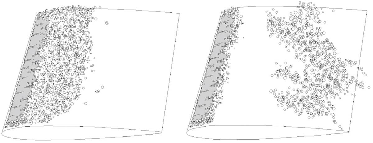
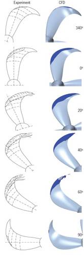 Figure 6: Both in the physical test and in the simulation, cavitation occurs between ҩ = 340° and ҩ = 90°, which shows good agreement in terms of type and form. (Image: MAN Diesel & Turbo)
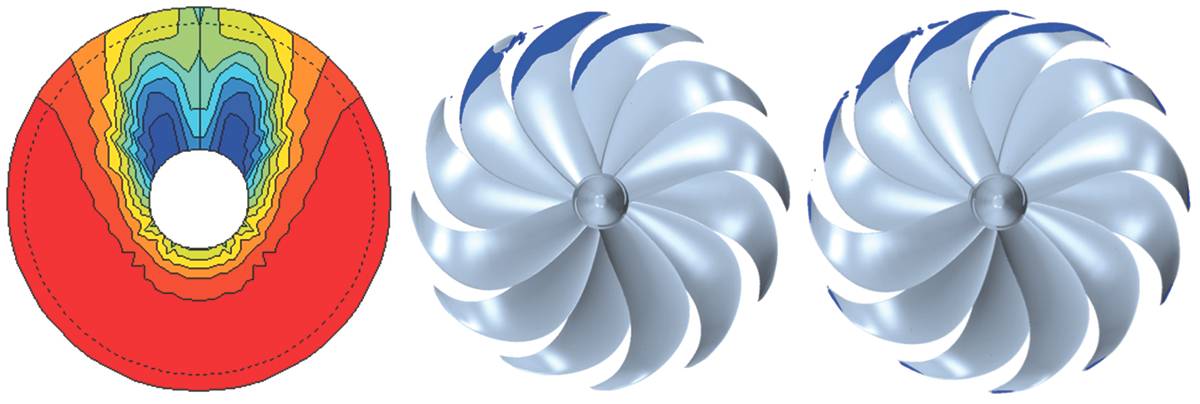
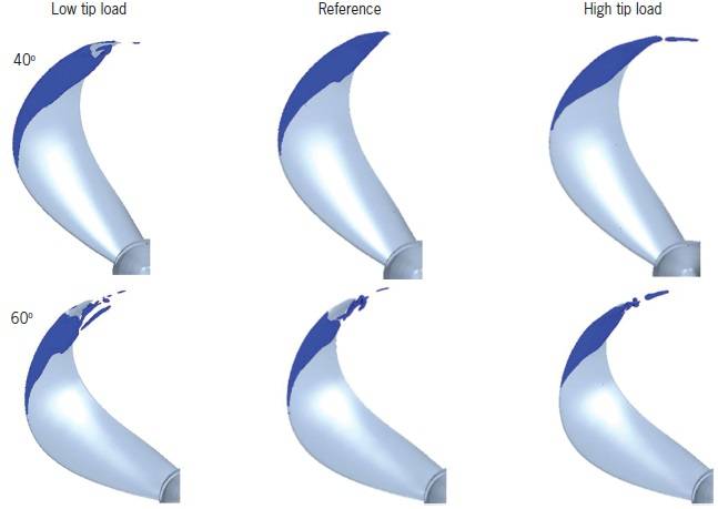 Figure 7: CFD cavitation on reference propeller and high & low tip-load variants (Image: MAN Diesel & Turbo)


MAN Diesel & Turbo optimizes the efficiency of ship propellers using cutting-edge CFD simulation methods
The layout of ship propellers is a balancing act between optimal power conversion and the avoidance of unwanted cavitation effects, which can result in damage to the propeller structure and higher noise levels. MAN Diesel & Turbo in Frederikshavn, Denmark, is using the computational fluid dynamics (CFD) simulation solution STAR-CCM+ from Siemens PLM Software to model cavitation and optimize ship propellers.
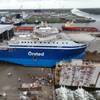
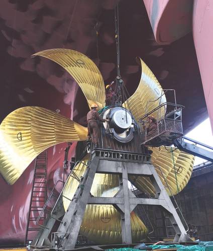
Two mid-size container ships of 8,500 TEU – CSCL Europe and CSCL America – will be upgraded by retrofitting a efficient Kappel propeller. It is powered by a MAN 12-cylinder, two-stroke diesel engine, which is capable of giving the propeller shaft a power output of 68,520 kW.
These dimensions are even more impressive when one considers that the entire power output has to be converted into propulsion as efficiently as possible by just a single propeller. Ship propellers for drives of this size have a diameter of 10 meters or more, weigh over 100 tons and are manufactured with high precision from special alloys, such as nickel-aluminum bronze or stainless steel alloys.
Ship Propellers – a Balancing Act
The greatest challenge for designers of ship propellers is to use the available engine power as efficiently as possible in order to minimize fuel consumption and therefore operating costs: a mid-size container ship will consume bunker fuel at a rate of more than 100 tons per day. At a cost more than $300 per ton, even marginal improvements in fuel economy will lead to significant savings.
However, propeller designers do not have unlimited freedom, a propeller designed with too much emphasis on power output can produce various cavitation effects, which can result in undesirable vibrations and noise levels and give rise to erosion of the propeller structure.
In addition, the propeller does not act within a nice homogeneous flow field, but in the wake of the ship’s hull, and the propeller blade passes through various flow regions with different pressure and speed ratios during each rotation.
MAN Diesel & Turbo
Dr. Keun Woo Shin is a research engineer in the Propeller & Aft-Ship R&D department at MAN Diesel & Turbo in Frederikshavn, Denmark, and is very familiar with this problem. As a member of the propeller R&D team, He has been working intensively for many years on the CFD-based optimization of ship propellers as well as on related topics, including simulations incorporating the effect of the wake, cavitation simulations including an estimation of the erosion risk, and the analysis of scaling effects.
MAN Diesel & Turbo is a leading supplier of drive components for various types of ships. The company supplies shipyards with a wide range of engines, as well as complete drive trains (engine, propeller, shaft, aftship energy-saving device and propulsion control system) in which the individual components are optimally designed to suit each other and the specific application. The company designs and manufactures propellers with diameters of 4 to 12 meters and weights of up to 100 tons. Lead times for a “normal” propeller design are extremely short. As such, there was a strong impetus for adopting (and reaping the benefits of) modern simulation technology early on - MAN Diesel & Turbo have been using the CFD solution STAR-CCM+ from Siemens for the analysis and optimization of ship propellers and related areas of activity since 2004.
MAN was thus also a pioneer in encouraging a development that has led to numerical simulation techniques becoming a now indispensable part of the development chain at many companies. The range of applications is diverse and includes almost all areas relevant to shipbuilding, such as the hull flow, maneuverability, propeller design, seakeeping, etc.
Cavitation Simulation
Kappel propellers have become increasingly prevalent in recent years because they operate much more efficiently than conventional propellers. These propellers feature blade surfaces that are no longer helical, and they have tips that are very similar in shape and operation to the winglets on the ends of the wings on modern aircraft.
To achieve the greatest possible propulsion efficiency, a certain degree of cavitation is deliberately accepted in the design of modern ship propellers. However, too much cavitation can cause high pressure pulses on the hull, surface erosion on propellers and rudders and loss of propulsion.
In order to investigate the factors that cause cavitation in more detail - and to find an optimal compromise between propulsion efficiency and cavitation tendency/formation - Dr. Shin carried out investigations at MAN Diesel & Turbo on the effect of a modified geometry of the propeller blade tips of Kappel propellers. In order to have a reliable basis for comparison, a reference model was chosen--a Kappel propeller with four propeller blades for which test results from experiments in the cavitation tunnel were available. The experiments were carried out at the SSPA in Gothenburg, Sweden, on a complete model of a ship. The propeller model had a diameter of 250 mm (original size d = 5.9 m), with a curvature of the blade tip towards the suction side and a low area ratio of Ae/Ao = 0.38. The experiments were carried out with a flow velocity of 4.5 m/s and a propeller speed of 24 RPS and the cavitation number was 3.8. A high degree of sheet cavitation was observed, which is detached near the front edge and forms a cavitation cloud.
Propeller Variants with Varying Loads on the Blade Tips
From the reference model, two variants with a modified pitch distribution of the blade tip were then derived. In the case of the reference propeller, the reduction in the pitch compared to the maximum pitch was 35 percent, while a reduction of 10 percent and 60 percent was chosen for the variants. Compared to the reference propeller, the propeller variant with the small reduction has a higher load, and the one with the larger reduction has a lower load at the blade tip.
The CFD solution STAR-CCM+ version 9.02 from Siemens was used for the calculations, for which the DES method (detached eddy simulation) was chosen, as cavitation detachment and erosion risk can be predicted with greater precision with this than with the RANS method (Reynolds-averaged Navier-Stokes). In spite of this, the calculation effort is lower than that for a large eddy simulation (LES); this is an aspect that should not be overlooked, especially with regard to the routine use in the design process.
The cavitation model implemented in STAR-CCM+ was used. This is an Eulerian multiphase model using the VOF approach, whereby the phase interaction is mapped by means of a cavitation model based on the Rayleigh-Plesset equation. The influence of hydrostatic pressure was taken into account by considering gravity.
CFD Model
Computation grids with several million cells are generally used for CFD simulation in the maritime domain. While relatively small meshes with 1 to 2 million cells are sufficient for a simplified calculation of the propeller blade, 5 to 6 million cells are required for a complete propeller simulation with or without consideration of the hull wake. If the entire hull is included in the simulation, grids can comprise up to 20 million cells. The same order of magnitude also applies to cavitation simulations of propellers and rudders.
Hull Flow
While the physical experiments were carried out on a complete ship model, the simulation used the axial (velocity inlet) and transverse (momentum source) flow components determined from a separate simulation of the hull flow according to a method developed by Dr. Shin as inflow boundary conditions for the computational space. The experiment without a propeller showed good agreement for the axial flow, whereas the upward flow observed in the experiment did not occur in the CFD simulation.
Model Generation
For the purposes of this task, a computation grid was generated in which the propeller is surrounded by a rotating grid, but the rudder is outside the rotating region. A rigid body movement was assumed and the transition between the computational space and the rotating mesh was carried out using a sliding mesh. Cylindrical mesh refinements were made in the region of the expected cavitation detachment.
For the propeller, a trimmed hexahedral mesh with Δx = 0.5-1.0 mm on the wall surface and Δx = 0.1-0.5 mm on the blade edge was generated. For the description of the boundary layer, six layers of prismatic elements (Δh = 0.12-0.25 mm) were generated on the blade surface.
The simulation began with relatively large time steps, corresponding to an angle increment of the propeller rotation of 5°. As soon as stable flow conditions had been established (4 to 5 revolutions), the time steps were reduced (Δt = 116 μs) in order to correspond to an angle increment of 1°, so as to detect small changes in the non-uniform cavitation.
Results of Cavitation Simulation
It was found that the calculations carried out on the reference propeller showed a high level of agreement with the experimental data, thus meeting a basic prerequisite for drawing reliable conclusions about the variants.
The shape, extent and form of the calculated cavitation demonstrated good agreement with the experimental results. Cavitation occurred between φ = 340° and φ = 90°, with sheet cavitation turning into a tip vortex being observed around φ = 40°. Likewise, good agreement was achieved with regard to the formation and detachment of sheet cavitation and the formation of a large amount of cloud cavitation. Compared to the reference propeller (24 RPS) at equal loading, a reduction in the sheet cavitation can be achieved by reducing the propeller speed by 0.5 RPS for the high tip-load propeller (tip pitch reduction 10 percent). However, tip vortex cavitation then occurs, which reduces propeller efficiency by 0.5 percent. In the propeller variant with low tip load (tip pitch reduction 60 percent), sheet cavitation increases with an increase of the propeller speed of 0.5 RPS, and cloud cavitation is intensified.
An abrupt reduction in blade tip load results in pronounced cloud cavitation. However, if the load is lowered gently, cloud cavitation can be reduced or avoided. However, it is necessary to accept a loss in efficiency due to the occurrence of tip vortex cavitation.
Conclusion
The results of the investigations carried out can be regarded as successful in several respects.
- The simulation results demonstrated good agreement with the onset and extension of cavitation in the physical tests under the assumptions provided and the boundary conditions.
- It was found that the method outlined here, of including the wake in the calculation without including a hull model, is effective and feasible.
- The DES (detached eddy simulation) method used for these investigations is suitable for predicting the occurrence of cloud cavitation.
Cavitation
Cavitation is the formation and implosion of cavities in liquids. It occurs when the hydrostatic pressure falls below the evaporation pressure of the liquid due to high flow velocities. Vapor bubbles are formed, which are entrained by the flowing liquid into areas of higher pressure, where the vapor in the cavities suddenly condenses and the vapor bubbles collapse. The ship propeller is considered one of the main sources of onboard noise and vibration and the correct determination of cavitation extension is crucial in securing the comfort of passengers and crews. Cavitation on the surface of solid bodies can cause microscopic deformation of the surface material due to the high mechanical stresses. Over time, larger particles break off the surface. Different types of cavitation include sheet cavitation, cloud cavitation, tip vortex cavitation, and supercavitation.
The Authors
Keun Woo Shin, MAN Diesel & Turbo & Ulrich Feldhausm, Feldhaus Marketing & Datentechnik
(As published in the August 2017 edition of Maritime Reporter & Engineering News)
Keun Woo Shin, MAN Diesel & Turbo & Ulrich Feldhausm, Feldhaus Marketing & Datentechnik
(As published in the August 2017 edition of Maritime Reporter & Engineering News)