
The Value of 3-D CAD in Ship Repair


The demand on naval and commercial fleet assets has never been greater than it is today. Owners and operators are looking to reduce their current year capital expenditures as much as possible, which in turn is pushing the currently operating vessels into longer than planned service lives. This industry trend is driving a greater number of complex repairs, overhauls and large service life extension programs. In order to support this effort, the industry has started to turn to 3-D Computer Aided Design (CAD) as a repair and overhaul tool.
Historically, 3-D CAD has been used by the maritime industry only as a new construction tool, and perceived as being too expensive and too complex to be used effectively for repair and overhaul. Over time,3-D CAD has become a powerful and efficient tool for ship repair projects as the technology of software and hardware has advanced and become more affordable. In addition, repair shipyards have become increasingly part of the design process and more reliant on computer aided planning, control and manufacturing processes.
Use of 3-D CAD for any project is a balance between the value of having a 3-D CAD design and its associated computer-aided manufacturing (CAM) support benefits versus the cost and effort required to develop a 3-D CAD model for the project. Alternative methods of developing design data, such as red lines to existing drawings, development of 2-D CAD drawings, or replacement in kind are all viable alternatives depending on the repair work under consideration. Each alternative needs to be considered in the context of its impact on:
• Design costs
• Shipyard industrial costs
• Schedule
• Risk mitigation
• Enhanced producibility
• Quality control
• Requirements management (e.g. weight control)
• Material management
• Manufacturing
• Impact to repair milestones (e.g. undocking)
Other issues that are taken into consideration include the availability of design data (in particular already existing 3-D CAD new construction models), the complexity of the repair, the degree and accuracy of design data needed by the shipyard, and the potential for enhanced coordination between the different engineering and industrial team members (e.g. use of CAD model split and merge, web based virtual walkthroughs, automated Bill Of Materials, parts numbering and ordering control). In addition, consideration is given to the ability to limit the extents of the CAD model to the local area in the vicinity of the repair, and limit the fidelity of the model to suit the shipyard needs for the specific repair.
This assessment is performed in a collaborative environment that includes engineers, designers, shipyard production leads and management to determine the best design approach to apply. This often includes a combination of the design alternatives noted above, optimized to suit the total repair package needed by the shipyard. For example, for a complex repair with tight manufacturing tolerances, a tailored CAD model would be developed, while for a simple change out of equipment, a work order specifying replacement in kind would be issued. This initial assessment and agreement between the design agent and the production leads is crucial in any repair and especially in a complex repair where CAD is being considered.
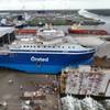
A recent ship repair project where a ship had crashed into a pier and experienced bow damage above and below the waterline illustrates the value of 3-D CAD in repair operations. The shipyard was facing very tight schedule constraints and needed us to help them accelerate the assessment of the damage, and develop a cofferdam design that they could use to allow access to the damaged area without dry-docking the ship. The cofferdam needed to be designed to tight tolerances in a complex area of bow structure to assure proper fit-up.
We immediately sent a naval architect to the shipyard who, with shipyard personnel, assessed the situation, took digital pictures of the damage, and used a 3-D CAD surface program to model the damage and the nearby bow structure. This was sent electronically to engineers in our main office who analyzed the data and developed the cofferdam design, which was then transferred to our design office to be detailed in 3-D CAD. The detailed CAD design was then electronically sent to our field engineer, who presented this model to the shipyard on his laptop within two days of his initial ship check instead of the 3-4 weeks it would have taken to loft the repair package by hand. In addition, a 3-D model of the damaged portion of the ship’s bow was developed, using the structural scantling drawings for the ship. This model allowed us to check proper fit of the cofferdam. The net result was that the shipyard was able to cut and assemble steel parts for the cofferdam and hull repair using CAM data from the 3-D models and the ship repair was completed in weeks, not months, without tying up the shipyard’s already booked dry-docks. In the end, the ship owner saved valuable time and costs with the aid of this technology.
In addition to providing CAM data for industrial cutting and shaping machines, 3-D CAD modeling can also be used to develop repair processes and procedures. Questions of producibility such as “Can a welder fit in the space to make the weld” are difficult to answer in 2-D but can easily be checked in a 3-D model. 3-D models are often used as a tool in studies for special projects such as repowering, hull plugs and mission changes. It allows everyone to clearly visualize the final configuration and prevent issues such as interferences, auxiliary equipment issues and tear out and replacement accessibility while ensuring that the client’s objective is still met.
As technology advances, CAD tools are becoming faster, more user friendly, more portable and cost effective. In addition, other advances, such as digital scanning, aid in the rapid development of 3-D models of existing spaces. These advances can allow rapid development of tailored 3-D CAD repair models, even during transit of the ship to the shipyard, allowing design and planning to proceed in advance of ship arrival, facilitating future repairs on schedule, within budget and technically correct.
The bottom line is that 3-D CAD can be extremely useful not only in new design/construction projects, but also in repair/sustainment projects where the complexity or desired level of integration between engineering, design, material management and manufacturing is high; whether or not there is accurate 3-D CAD information already available for the ship under repair. The cost of using 3-D CAD can be minimized by using available 3-D design data, limiting the scope of the model to the portion of the ship under repair, and tailoring the level of detail in the model to suit the needs of the repair project. As the trends of software capabilities increase and costs decrease the cost benefit analysis will continue to evolve and allow for the use of more and more 3-D CAD modeling for repair and sustainment projects.
About the Author:
Ben Capuco is the Vice President of Platform Solutions and has been employed by Gibbs & Cox, Inc. since 1986. He has been involved in all phases of vessel design for new construction and repair of Naval, Coast Guard, Oceanographic and commercial vessels. He can be reached at [email protected]
(Reprinted from the March 2012 edition of Maritime Reporter & Engineering News - www.marinelink.com)