
Realistic Engine Simulation


Abaqus FEA and XFEM for a Weld Redesign Against Fatigue Cracks
A century ago this year, the first ocean-going diesel ship in the world, the M/S Selandia, embarked on her maiden voyage. She was a technological wonder, and both her hull and engines were built by Burmeister & Wain (B&W) of Copenhagen, Denmark.
B&W is now a part of MAN Diesel & Turbo — a company with 12,000 employees worldwide — and the marine low-speed business unit is located in Copenhagen. The unit has capitalized on B&W’s historic expertise to produce new engines that can weigh up to 2,800 metric tons and tower 16 meters high. Once such behemoth engines are installed, they have to be serviced in place—and they must require servicing as infrequently as possible.
Reliability and durability, over a long and demanding life, are crucial to marine engines. They are built to perform over 30 years, roughly 6,000 hours a year, at a constant speed of about 100 rpm—a billion revolution cycles on full design load. Under these grueling conditions, fuel combustion and inertia of moving components can potentially cause high-cycle fatigue failure. “It’s vital that every part of our engines is designed and analyzed with sufficient safety margins against fatigue loads—right down to the welds,” says Tore Lucht, industrial researcher at the R&D department of the marine low business unit in Copenhagen.
Simulation of cracks: A strong tool to design against weld fatigue
The criticality of paying full attention to every single weld detail in the huge complex engine structure became a focus for R&D when a butt weld on a low speed marine diesel engine developed a crack. The weld was on the face of a second order compensator, a large rotating component that dampens engine vibration for greater crew comfort. While the compensator was designed to withstand large loads and stresses, the engine had only been in service two years, logging 13,000 hours and approximately 78 million revolutions of the crankshaft when the crack was observed.
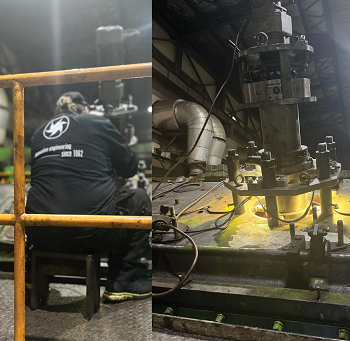
The R&D department conducted a preliminary investigation using Abaqus finite element analysis (FEA) from SIMULIA, the Dassault Systèmes application for realistic simulation. “We switched to Abaqus several years ago because we found it was the best tool for simulating engine structures,” says Lucht. “We use it for all structural calculations of our low-speed engines.” In the initial investigation they modeled a small cut-out from the engine undergoing centrifugal force from the flyweights (see picture above). The centrifugal force was that of a MAN B&W 5S60MC-C diesel engine at 100% rpm—a 16-metric-ton load. The engineers were able to simulate all these loads accurately based on decades of field data from operating engines. “Our engine analyses are highly realistic,” Lucht says, “because we put so much effort into benchmarking against literature, measurements, and service.”
The initial simulation showed that small areas of the weld root had stress levels above a reasonable design limit. A different weld design might significantly reduce stress amplitude and solve the problem, but how could the engineers make sure that the improvement was sufficient? “Clearly more investigation would be required to determine a repair procedure and a suitable weld for future engines,” Lucht says.
The International Institute of Welding (IIW) recommends three different methods to analyze welds: hot spot stress, effective notch stress, and fracture mechanics. The first method evaluates the weld by comparing structural stress at the hot spot to the FAT (fatigue) class of different weld details. Effective notch stress analysis can assess both toe and root stress level, again comparing each to a special FAT class. Fracture mechanics can be used to simulate typical weld defects on any part of the weld, using linear elastic fracture mechanics (LEFM).
Based on previous research projects and experience, the analysts at the R&D department decided that LEFM would give them the most accurate answers, even though it potentially involved a great deal of model preparation. “The applied meshing of the crack can be very time-consuming because a special mesh is required along the crack front,” says Lucht. However, the team employed Abaqus’ eXtended Finite Element Method (XFEM) technology, which reduces modeling time while offering an enriched environment for exploring fracture failure, even when the crack doesn’t follow element boundaries. Lucht adds, “Since we already had advanced numerical models of our engines in Abaqus, that cut simulation time even further.”
The engineers submodeled the area of the crack in XFEM with a fine mesh. “Investigating a crack of a few millimeters growing in a four-story engine undoubtedly requires some mesh refinement in the pertinent area,” Lucht says. “This submodeling strategy made our task easier and less time-consuming.”
Opting to model the most severe dynamic loading on the crack, the engineers excluded contact in the crack definition, leaving a weld gap—which could occur in such a structure due to either residual stresses from welding or from a slight misalignment between the parts that the weld joins.
After calculating the stresses on the original design, the engineers performed similar analyses on proposed welds for the engine repair and for weld designs on new engines going forward. One final load check was needed to confirm that the repair was sufficiently strong: the residual stress state caused by the welding process itself. This stress was not included in the other LFEM calculations, and it could potentially alter the strength of the final weld. To determine the residual stress state of the weld, the R&D department used a weld simulation tool for Abaqus developed in a previous research project with the Technical University of Denmark: a specialized modeling principle for simulation of a moving heat source by weld filler, body flux and surface flux. The simulation adds the weld filler incrementally, with the elements representing the weld filler assigned a temperature above its melting point.
The elements were activated in groups with the model change command and with predefined values of temperature, body flux, and surface flux. New groups were automatically activated in subsequent steps as the old groups cooled as a function of the heat transfer. “Realistic simulation of the moving heat source of the weld is a key to this type of simulation,” Lucht says. “By adjusting the active parameters like weld sequence, heat, and flux, it has been possible to obtain a high level of validation by comparison to experiments using methods like neutron diffraction measurements.”
In this case, the simulation helped the engineers see the result of welding an additional supporting structure onto an engine. This predicted both the deformation of the existing engine structure and the size of the residual stress field around the crack front. The analysis assumed that filler material was welded in only three strings, and the welding was simulated along the side of the model, where it would introduce residual stresses perpendicular to the only critical weld defect that could cause an opening or closing of the crack.
These final simulation results enabled the engineers to relate both the residual welding stress fields and the crack simulation to obtain realistic fatigue assessments. As expected, large tensile residual stresses remained at the toes of the weld, but the stress level was close to zero at the weld’s root. This meant that the stress intensity factor evaluation of the critical root of new weld designs would only be marginally influenced by the residual stresses of welding.
“Even so,” Lucht points out, “It would be good practice to take precautions, such as adding a peening step to the weld toes, to limit the influence of high tensile stresses on the safety margin against fatigue failure, so that we don’t introduce a new problem with the repair.”
Analysis Results: Clear Sailing Ahead
Realistic simulation revealed why the original weld design performed as it did and confirmed that the new design would be safely within the recommended limit curve. The demonstrated lack of tensile stress in the weld root proved out the integrity of the new design. “This combined method of weld process simulation and fracture mechanical evaluation of weld defects with XFEM is a strong tool to evaluate the structural integrity of complex welded structures,” says Lucht. “From this analysis, we were able to verify that our new weld design is safe, both for repair of existing engines and for use in future engines.”
(As published in the May 2013 edition of Maritime Reporter & Engineering News - www.marinelink.com)