
Finite Element Strength Analysis for ATB Load Box


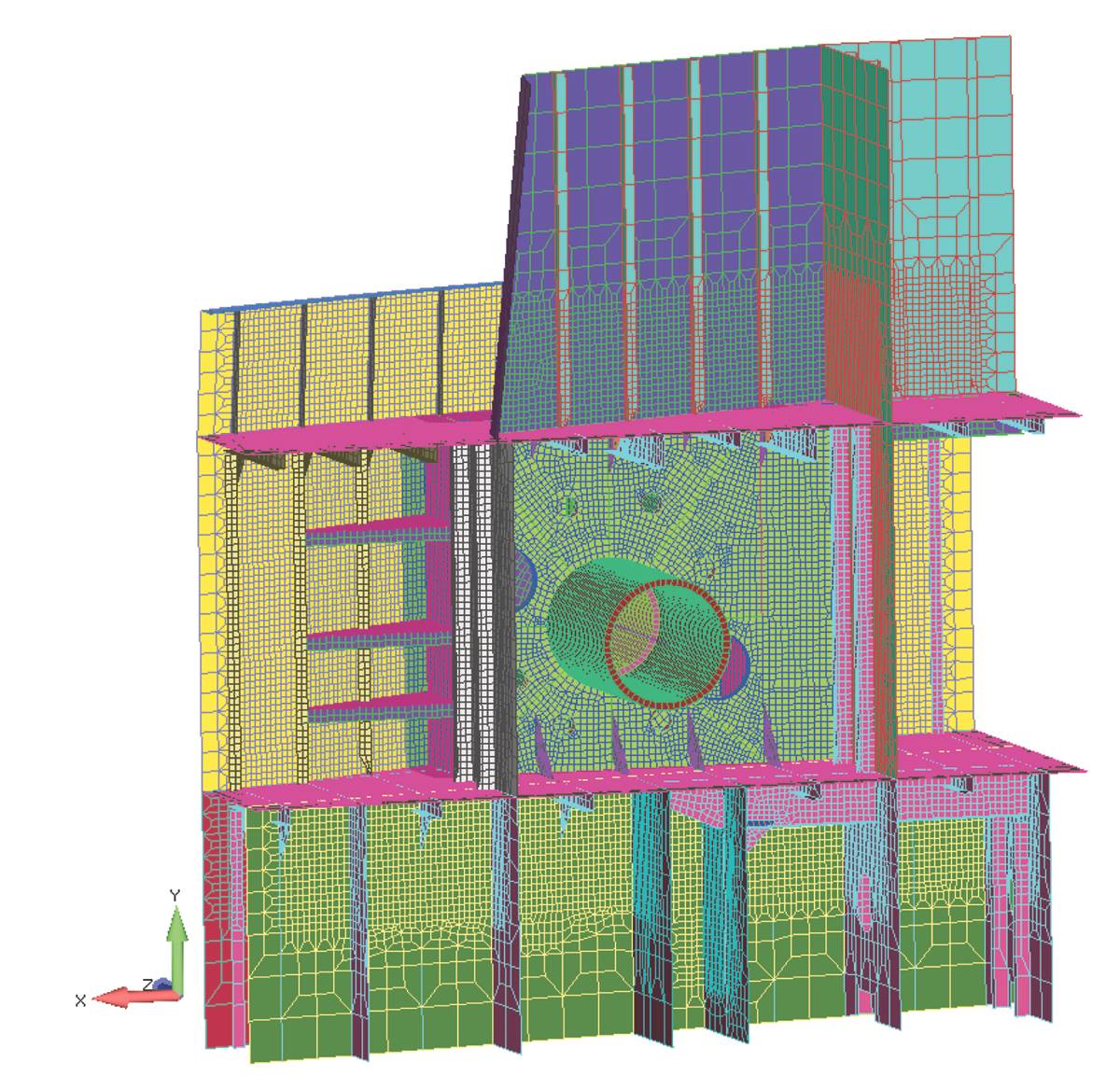
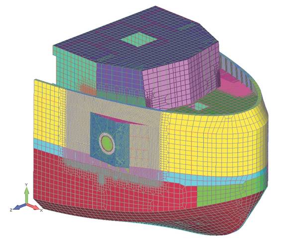 Figure 1: View of Global Finite Element Tug Model.
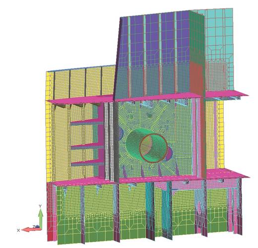 Figure 2: Refined Structure in Way of Load Box.
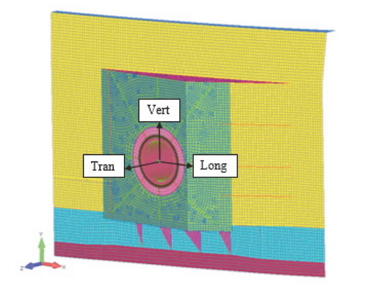
 Figure 3: Load Application.
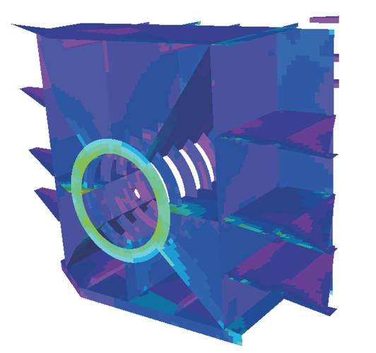 Figure 4: ABS Load Box Yielding Evaluation Plot.
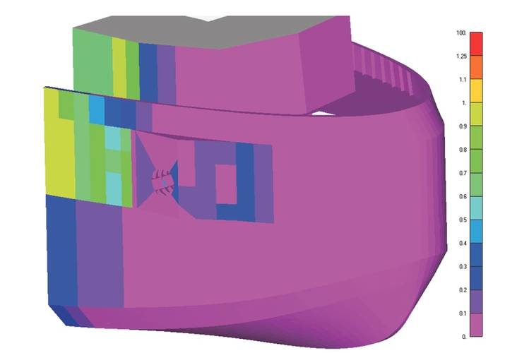 Figure 5: Color Coded Buckling Assessment Plot using ABS Rules for Multiple Load cases.


The loading and response dynamics of an Articulated Tug & Barge (ATB) load box are complex. They typically require advanced finite element analysis methods and procedures to design an efficient support structure to ensure a durable design and to facilitate meeting Class strength requirements.
To study the dynamic response of the loads imparted on the tug from the barge, a finite element analysis (FEA) is carried out. Loading conditions that include the static sea pressure, gravity loads, and reaction forces from the ATB Coupler are incorporated into the FEA analysis. The initial step in this process is to analyze a larger global model for initial assessment, followed by detailed fine mesh analysis of the support box interface or elsewhere on the vessel’s structure. Results from the fine mesh analysis will allow for a detailed understanding of the stress concentrations and the changes required to make the design successful. Modifications are then designed to the load box interface and tug structure itself, typically by scantling increases, material grade changes, addition of brackets and panel breakers.
The following editorial is based on a recent engineering project conducted by Viking Systems International to ensure the structure in way of the load box can properly withstand applied loads from an ATB coupler system while satisfying Class (ABS) rules. Particular focus is on the structure in way of the load box-to-tug connection, where the connection loads between load box and tug occur.
Typically load box structures are designed as a rectangular box structure that spans horizontally between frames in the bow region of a tug and vertically between the tug’s main deck and a particular sub-deck. For this type of assessment project, Viking employs a full breadth FE model including the original tug structure, new load box, and any transitional structure. A full breadth model is important to ensure that the torsional loading response between the tug and the barge is accounted for. The tug structure is modeled with as-built scantlings as required by “ABS Rules for Building and Classing Offshore Support Vessels”. The mesh density is refined in way of the load box and surrounding structure, with transverse web frames and bulkhead stiffeners modeled with plate elements of 50 mm x 50 mm mesh density. The rolled tube that makes up the hydraulic cylinder and the internal ram section in way of the load box are both modeled using solid elements. All other structures are modeled with a mesh size that corresponds to the two elements between transverse frames.
The tube and ram are designed by the manufacturer and are included in the support structure model to provide proper stiffness and accurate transfer of loads into the support structure. The rolled tube and internal ram structures are modeled with solid elements to more precisely distribute the reaction loads from the ram to the load box. Applied loads are developed using a combination of local interface, pressures, and acceleration load components correlating to a number of tug and barge design loading conditions.
The reaction loads simulating the interaction of the tug and barge are applied as a single point load to the center of the ram. A contact field of elements is created on the ram and cylinder to simulate the contact surfaces that transfer the load from the ram to the cylinder. A loading condition matrix is developed to combine the coupling system reaction load application directions (forward/aft, up/down, and port/starboard) with the dynamic motions and loads of the tug. A typical analysis uses approximately 50 to 75 load cases developed to adequately represent design load combinations.
Applied tug loads include static and dynamic accelerations as well as sea pressure correlating to both calm and heavy weather environments. Internal tank pressures are also applied as needed.
Once the loads are generated and the stress results are available from the finite element solution, Viking’s structural assessment software, SAGA, is used to evaluate the design against the resulting stresses and displacements for each load case. This is completed using Viking’s SAGA database system enabling rapid assessment amongst all design load cases for structural yielding and buckling capacity. Yielding evaluation for the plated structure of the model is based upon membrane elemental mid plane stress. Assessment unity ratios are calculated by comparing resulting stress against the allowable stress limits published by ABS which are dependent upon the mesh size used in the analysis. The entire area of interest in way of the support structure for the load box are modeled with a nominal mesh size of approximately 50 mm, followed by fine mesh models to verify the structure satisfies the ABS criteria. The processing of the response stress and structure material strength limits are automatically done using Viking’s SAGA post processing module for different mesh sizes.
Similarly to the yielding evaluation, a buckling assessment is performed in accordance with the ABS Guide for ‘Safehull – Dynamic Loading Approach’ for vessels using SAGA’s post processing module. The plate panel buckling assessment is calculated using the panel average stresses from the finite element analysis, by aligning the resulting stresses to be in the panel directions in order to allow the use of both the uniaxial buckling rules as well as biaxial and shear buckling rules using the equations from Class (ABS) rules. A buckling assessment ratio is then obtained for all panel and design load cases by use of panel dimensions, thickness and stresses by comparison to the ABS critical buckling stresses for the panel.
In the case of this recent design assessment on a tug, a number of minor modifications and additional pieces of steel were easily designed using the same assessment process as described above, providing the owner and the shipyard with a simple solution prior to start of construction. However, for a conversion or a structure already built, the addition of new steel only, such as brackets, is typically used to mitigate issues of yielding, buckling and fatigue while obtaining an efficient structural solution for the owner and the shipyard.
The Authors
Fritz Waldorf is Director of Sales and Marketing for Viking Systems International and based in Viking’s Houston office. Viking assists shipyards, ship designers and owner/operators with efficient implementation of advanced analysis tools for floating vessels and structures.
Matthew Schubert is a Senior Engineering Manager at Viking Systems based in Viking’s Annapolis, Md. office. He has managed the analysis of multiple ATB new build and conversion projects utilizing Viking’s advanced analysis procedures for both tug and barge structures as implemented in SAGA.
(As published in the May 2017 edition of Maritime Reporter & Engineering News)