

How to Calibrate an AC-operated LVDT Linear Position Sensor

Calibration is necessary before the installation of an AC- operated linear position sensor to ensure accuracy. Calibration corrects any slight variances between sensors, helping to improve repeatability.
Because of the linearity of LVDT Sensor output, a simple two-point calibration is simple. Two points should be as far apart as possible, but within the linear range of the LVDT Linear Position Sensor and preferable within the measurement range in which it will be used.
In applications where the LVDT is used on both sides of null, the calibration points should span the entire range of measurement. In these cases, it is desirable to use three calibration points: one at null and one at each end of the range.
Calibration should be performed as nearly as possible under conditions of actual use, including the same mountings and surroundings as well as the same excitation voltage and frequency.
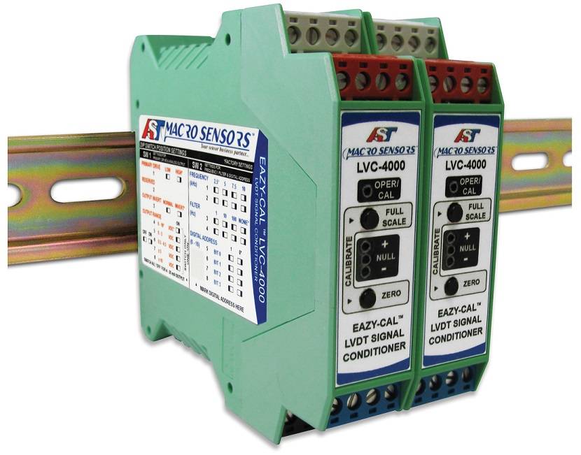
Traditionally, AC-operated LVDT Sensors were difficult to calibrate as signal conditioners required that operators use trimmer pots. Modern signal conditioners, like Macro Sensors EAZY CAL Signal Conditioner , offer a virtually effortless front panel fingertip routine for easy field calibrations.
Macro Sensors has provided a video that shows the calibration of a LVDT linear position sensor using the EAZY CAL Signal Conditioner, explaining suggested calibration equipment, mechanical mounting of the signal conditioner, input and output connections, LVDT wiring, core position and the calibration routine: youtube.com/watch?v=pEOpI_ym2E8.
macrosensors.com