
Answering the Call for Environmental Answers


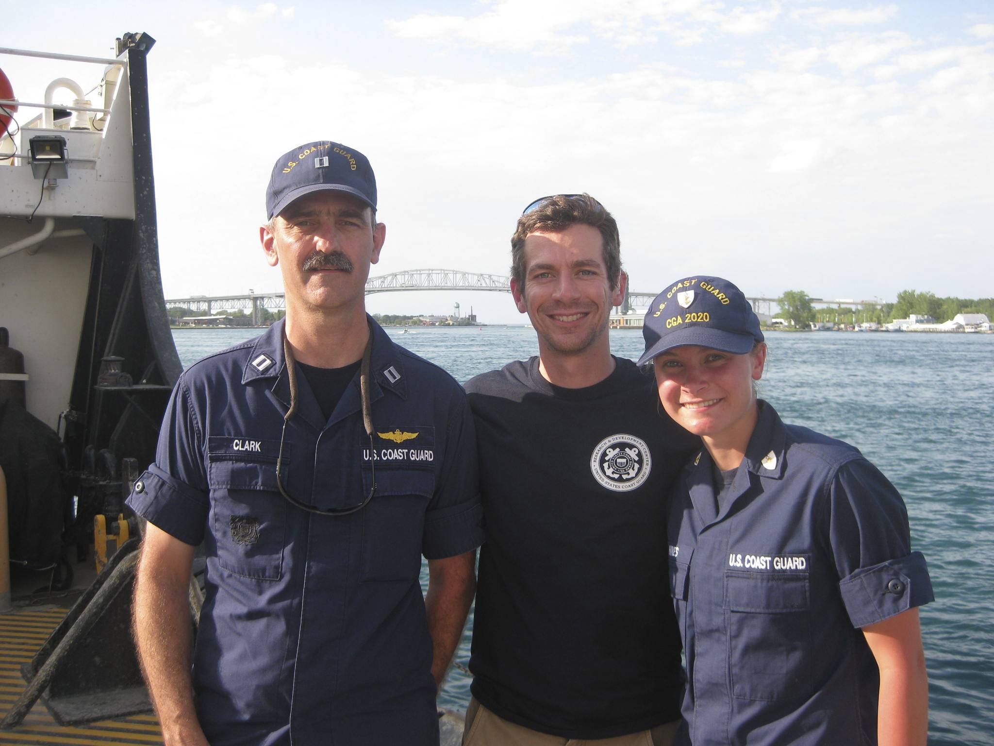
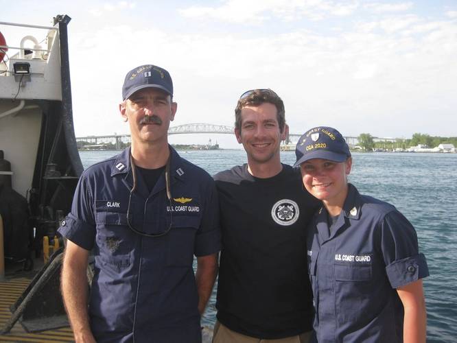 The RDC project team poses on USCGC Hollyhock after completion of the offshore mitigation system prototype test. From left to right, LT Charles Clark, Alexander Balsley, and Coast Guard Academy Cadet 2/c Valerie Hines.)
 Alex Balsey
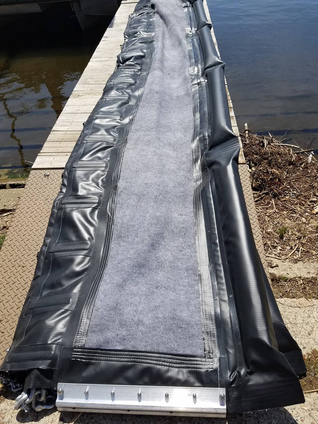
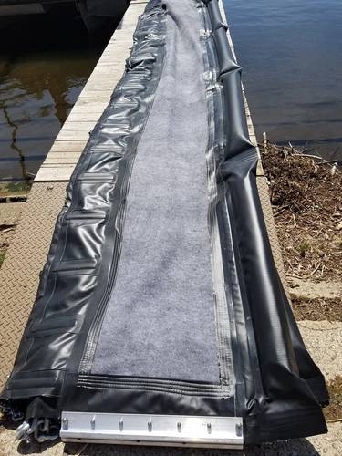 The inland mitigation system prototype that shows the incorporation of the X-Tex fabric into the barrier design. This is meant to deflect oil towards the shoreline for easier recovery.

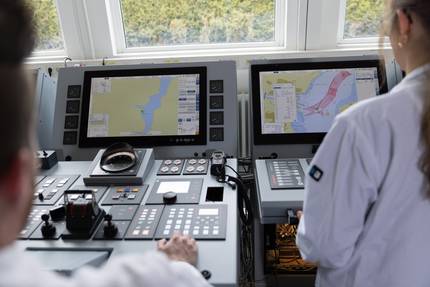
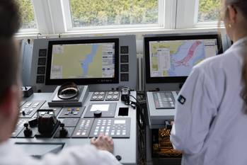
The Coast Guard has developed two separate mitigation system prototypes specifically designed for inland and offshore environments and tested them in the Kalamazoo River and Lake Huron.
Whenever there is a need for oil, there will always be a risk of oil spills. This is no less true for bituminous sands, commonly known as oil sands or tar sands. Oil sands are mostly found in Alberta, Canada, and comprised of bitumen, sand, clay and water. They are typically viscous, with a texture similar to peanut butter. Alberta’s oil companies transport their product to coastal refineries outside of landlocked Alberta. One method of transport involves adding diluents, such as natural gas condensates, to oil sands to reduce viscosity and make transportation by rail or pipeline easier. The new product blend is called diluted bitumen, or dilbit.
Today, scientists and researchers continue to study dilbit’s properties as well as its fate and behavior if spilled into the environment. Dilbit’s characteristics are similar to that of crude oil, but real world experience demonstrates that it behaves differently during a spill incident. In 2010, approximately 877,000 to 1 million gallons of dilbit flowed into the Kalamazoo River from a burst pipeline. Over 20 miles of shoreline were affected, making it one of the largest inland oil spills in U.S. history. Responders faced the atypical challenge of trying to mitigate the impacts of moving, sunken oil. The U.S. Environmental Protection Agency (EPA) On-Scene Coordinators and Oil Spill Removal Organizations (OSROs) tried several approaches to recovering the moving, sunken oil with varying degrees of success. It was evident that a better mitigation approach was needed not only for oil spills in rivers and streams, but for other potential dilbit or non-floating oil spills in the nearshore and large lake environments.
- Finding a Better Way
In 2016, the U.S. Coast Guard Research and Development Center (RDC) took on this challenge and began projects to identify, design, and test new methods for responding to non-floating oil spills, including detection and removal of sunken oil on the bottom and suspended in the water column. With funding support from the EPA through its Great Lakes Restoration Initiative (GLRI) program, the Coast Guard developed two separate mitigation system prototypes specifically designed for inland and offshore environments and tested them in the Kalamazoo River and Lake Huron, respectively.
The inland mitigation system prototype was test deployed in the upstream portion of Morrow Lake in Kalamazoo, Michigan, in April 2018. This location was selected due to its proximity to the Great Lakes where GLRI stakeholders would have an opportunity to observe the equipment and ask questions of the project team. Lake Huron was selected as the test site for the offshore mitigation system prototype for the same reason.
The inland mitigation system prototype includes a 75-foot barrier that consists of three separate 25-foot segments connected to each other. It was designed to deflect moving, sunken oil toward the shoreline, for use in fast waters with a current up to 3 to 4 knots. This design is intended to allow an easier recovery of sunken oil since it would be diverted to an area with minimal current. Two segments of the barrier (total of 50 feet) are 3 feet high with the last segment (25 feet) nearest the shoreline measuring 2 feet high to account for the decreasing water depth and lower current. The angle of barrier deployment (or angle of deflection) relative to the shoreline is dependent on the river current; the higher the current, the less the angle. This ensures that the barrier’s fabric material is not exposed to damaging levels of pressure exerted by the river current.
The barrier itself is comprised of X-Tex fabric and high-density polyethylene (HDPE) material with scour flaps made rigid by strips of fiberglass on both the upstream and downstream sides of the barrier. The primary purpose of the scour flap is to prevent oil entrainment, which is likely in regions of high current. The bottom of the barrier is weighted with steel link chains while the top is equipped with flotation to help keep the barrier upright during deployment.
In the Kalamazoo River, RDC tested two different anchoring methods for the inland barrier system, which are dependent on bottom substrate type and water depth. If the river is relatively shallow (less than 10 feet) and has a sandy bottom, the upstream portion of the barrier can be anchored to a post driven into the river bottom with the downstream end tied to a tree or other suitable fixture on the shoreline. In deeper waters or areas of river with harder bottom substrates, the upstream end of the barrier can be anchored to a Jersey barrier with the other end of the barrier tied to the shoreline. RDC was able to learn lessons about deployment and retrieval of the barrier and monitored several aspects of the barrier’s performance including position, motion, sag, scour, and tension using load cells, Global Positioning System (GPS) units, and video cameras.
- Offshore Focus
After conclusion of the inland barrier system field test in Kalamazoo, focus shifted to testing the offshore mitigation system prototype in Lake Huron near Port Huron, Michigan. U.S. Coast Guard Cutter Hollyhock, a 225-foot seagoing buoy tender, was used to deploy the offshore prototype, which was designed particularly for lower current environments (less than 2 knots) and for the purpose of collecting oil in a “U-shaped” configuration rather than deflecting (like the inland barrier system). This prototype is made up of four separate 50-foot sections that were connected for a total length of 200 feet. The barrier itself is made up entirely of HDPE, is approximately 3 feet high, and can be attached to the lake bottom with anchors and stakes with help from divers. Similar to the inland barrier system, it is weighted down with steel link chains, but the top is tied to buoys so that the barrier is able to stay upright as it is being deployed to the lake bottom.
Over the course of three days in May 2018, RDC tested barrier deployment in two different locations of the lake, one in a low current area (less than 1 knot) and another with slightly higher current. RDC collected lessons learned on how the barrier could be best deployed and retrieved. The barrier’s performance was monitored with video cameras and a sonar instrument.
- Today’s Research Yields Tomorrow’s Response Strategy
RDC continues to analyze its findings and will present preliminary results on these first two prototypes in New Orleans this November. RDC is also working to develop a third inland mitigation system prototype for testing at the same location in the Kalamazoo River in April 2019. After the third and final test is completed, RDC will report findings and recommendations about each of the three prototypes. The report will be made available to the public in September 2019.
RDC will end the project by developing a job aid that will describe equipment and tactics useful for detection, monitoring and response options for oil sands products response. This will be available to the public in 2020 and provide the full options for responding to oil sands products spills. With the development of these three prototypes to mitigate the impacts of moving, sunken oil, the Coast Guard will be armed with greater knowledge on methods to respond to these types of oil spills.
The Coast Guard Research and Development Center (RDC), located in New London, Connecticut, is the Coast Guard's facility for performing research, development, test and evaluation in support of the service's major missions. RDC is responsible for evaluating the feasibility and affordability of mission execution solutions and providing operational and risk-management analysis at all stages of the acquisition process. RDC also operates a Maritime Test Facility in Mobile, Alabama.
Alexander Balsley is an environmental engineer and has been a project manager at RDC since 2010. He is primarily involved with RDC’s Oil Spill Response program and is a subject matter expert in this field. Balsley has an M.S. in Environmental Engineering from Worcester Polytechnic Institute, and a B.S. in Civil and Environmental Engineering from Northeastern University. He is a registered Professional Engineer in Massachusetts.
This article first appeared in the September print edition of MarineNews magazine.