

USCG Reports: Small Fire, Important Lessons

The U.S. Coast recently published lessons learned resulting from a casualty investigation:
Recently in the North East an 83-ft long passenger ferry which has the capacity to carry 306 persons experienced a small engine room fire. The vessel was just off its dock at the time the fire started and onboard were 110 persons. Because of the nearness to the dock, the vessel’s Captain chose to disembark the passengers prior to manually activating the engine room CO2 system and closing the main fuel stop valve. The CO2 system extinguished the fire and when the local fire department arrived later they found the port main engine’s exhaust insulation smoldering. Using a fire hose to cool the area they completely extinguished the fire. Although the casualty is still being investigated, it appears that the fire was caused by a leaking pipe fitting attached to the fuel oil filter of the center engine. Fuel sprayed from the rear of the center engine to the port main engine exhaust piping and ignited.
Polypropylene or PVC Components
The engine room utilized vents to provide air for the engines and cooling. There were no forced supply fans or exhaust systems. Slots in the ceiling at the outboard sides of the engine room, forward and aft, provided the openings to four ducts which contained dampers. The damper closed against the slotted opening located in the floor of the duct (ceiling of machinery space) when the CO2 system was activated. In normal circumstances, airflow from the outside could flow past a moisture eliminating filter, into the duct area, past the open damper, through the slot and into the engine room. Depending on weather conditions, air could enter one side of the vessel and exit the other.
When the extinguishing system was activated, all the dampers closed properly. However, after the fire it was noted that several external moisture eliminator filters were extremely damaged. The actual size of this filter is about five feet by fifteen inches.
High temperature gases flowed through it during the fire causing it to overheat and deform prior to its respective damper closing. It fell on top of the damper after the damper had closed. The small fire in the engine room was about nineteen feet away on the other side of the vessel and aft. Investigators noted that if the filter had melted and fallen on or into the slot of the duct before the damper closed, it is likely to have interfered with the damper operation and possibly have reduced the effectiveness of the CO2 system.
46 CFR 116.610 (b) applicable to this vessel, states that “a ventilation duct, and materials incidental to installation must be made of noncombustible material.” 46 CFR 116.610(c) states that “combustibles and other foreign materials are not allowed within ventilation ducts. However metal piping and electrical wiring installed in a metal protective enclosure may be installed within ventilation ducts, provided that the piping or wiring does not interfere with the operation of fire dampers.”
Owners and operators of any type vessel, as well as those persons involved with the inspection of vessels should be aware of the potential risks associated with this and similar installations and are reminded that inspections of fire dampers should include observation of all related structure near dampers to ensure that the dampers will operate under fire conditions. These structures and any incidental materials should not be made of combustible material. On vessels with manual extinguishing systems, or those with manual dampers whereby when securing the ventilation time is of the essence, consideration needs to be given regarding the materials used should it be subjected to excessive heat carried by high temperature gases.
Failed Pipe Fittings
As stated previously, the investigation into this casualty is not yet complete. The components of the pipe fitting which failed are currently being examined by NTSB metallurgists. It is suspected however that the failed fittings may have been subjected to excessive vibration which could have caused the fracture. The original configuration was modified by adding a fitting that attached two additional sensors (for a total of four) to the fuel filter assembly and was subject to pressures up to 65 psig or greater. The assembly weighed 6.3 ounces and extended about 4 inches out of a reducing bushing that was threaded into the inlet fitting of the filter. Because of the location of the fire and oil soaked insulation it is suspected that the fitting leaked first and did not immediately shear as shown in the photo at the right.
Owners and operators of any type vessel, as well as those persons involved with the inspection of vessels should be aware of the potential risks associated by adding components to an engine assembly and must take into account the effect of vibration on those components. If add–on components are discovered effort should be made to verify the adequacy and safety of the installation by consulting the engine manufacturers and designers. In this instance an improved installation may have involved mounting the sensors directly to a stable surface and attaching the sensors to the filter inlet using a flexible hose.
Hot Spots
In a small engine room containing several engines and having a low overhead there are a number of locations that present enough heat to cause a fuel to flash and ignite other components. Turbocharger and exhaust piping insulation while serving to reduce heating of external areas also helps reduce the immediate availability of ignition hot spots. Care should be taken to ensure insulation wraps and blankets are kept tight and fastened in a manner to prevent dripping or spraying fluids from traveling to an exposed hot spot.
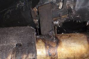
Insulation seams should be made tight and where possible aligned in a manner to prevent pooling of fluid and to repel dripping. Likewise good marine practice may also dictate and ensure that braces which are welded directly to the exhaust pipe which serve as hangers or supports also be insulated. Heat conducting from the exhaust pipe to the brace could be substantial allowing the exposed bracket to become nearly as hot as the exhaust pipe. The brace in the photo above was only partially covered with the insulation that was wrapped around the exhaust pipe. As with the other concerns in this document, owners and operators of any type vessel, as well as those persons involved with the inspection of vessels should be aware of the potential risks associated with improper or inadequate installation of insulation.
Additional fire protection information is provided in 1) NVIC 9-97 “Guide To Structural Fire Protection” available http://www.uscg.mil/hq/cg5/nvic/pdf/1997/n9-97.pdf and 2) IMO Maritime Safety Committee MSC.1/Circ.1321 11 June 2009, “GUIDELINES FOR MEASURES TO PREVENT FIRES IN ENGINE-ROOMS AND CARGO PUMP-ROOMS.” Copies available upon request.


