
Interview: Tim Leach, Glosten, Discusses Efficient Refit by Design


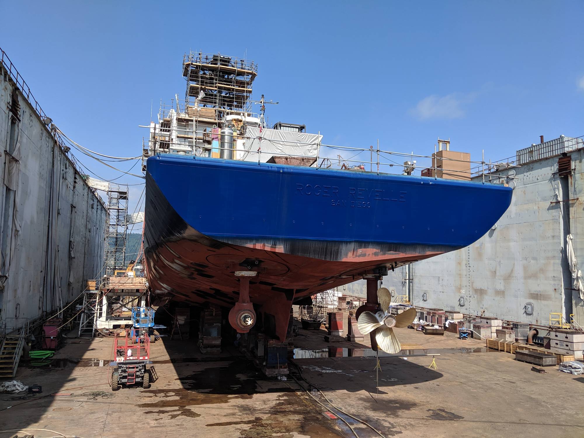
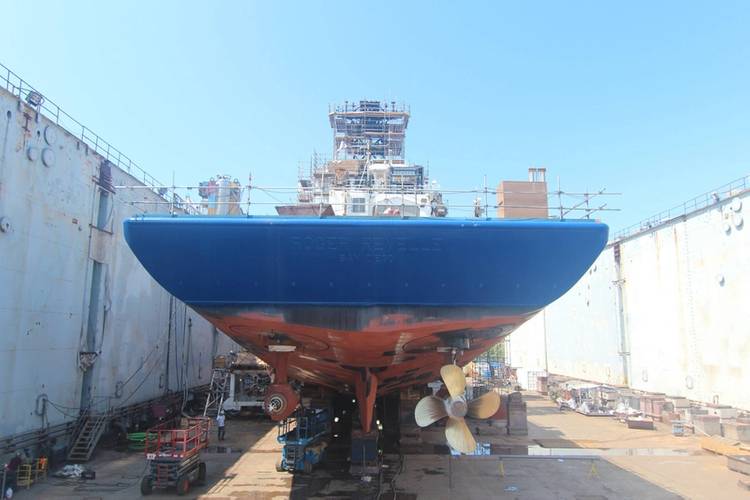 RV Roger Revelle in drydock. Image courtesy Glosten
 RV Roger Revelle in drydock. Image courtesy Glosten
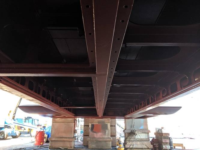 Making space for the new 'gondola'. Photo courtesy Glosten.
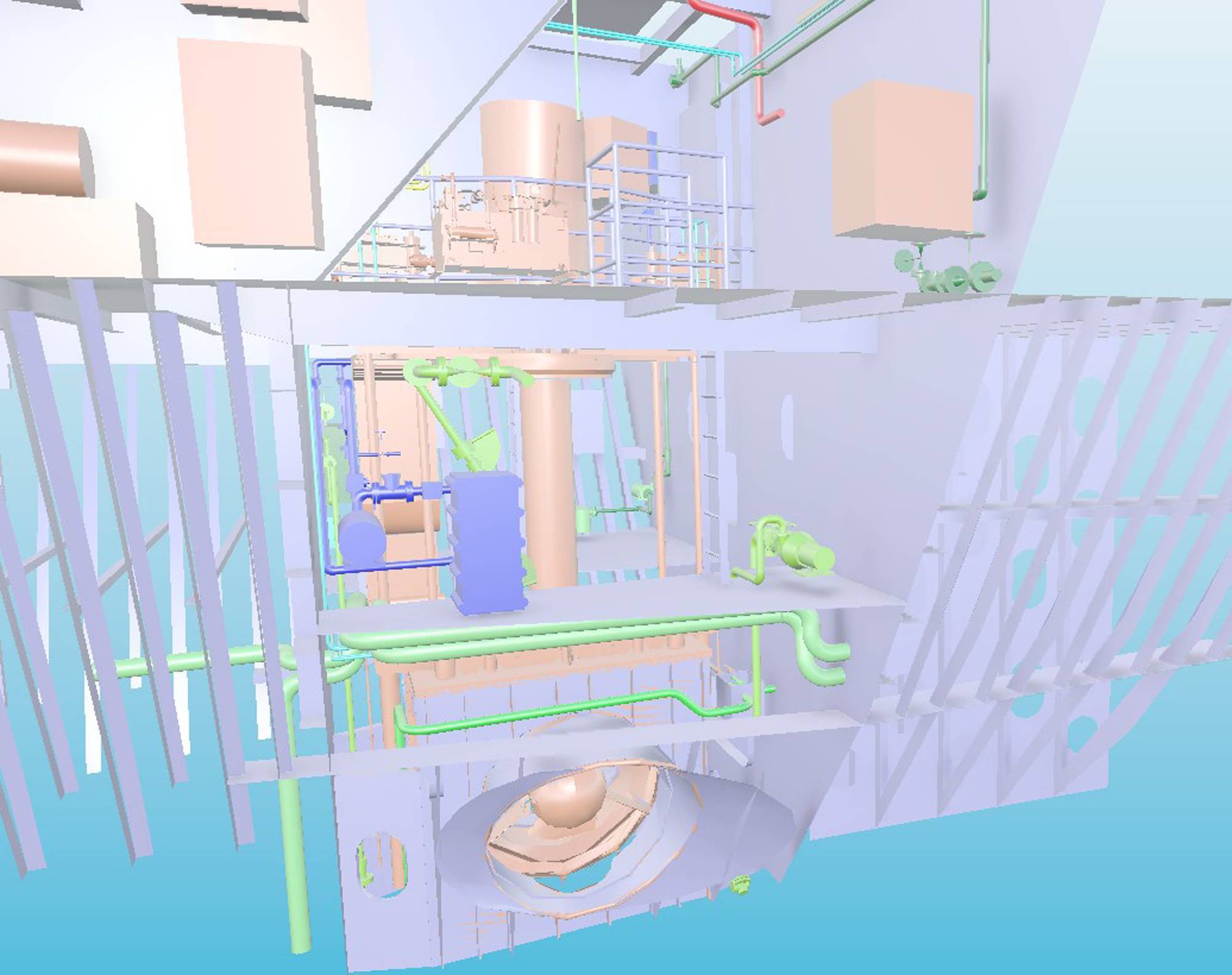
 Cadmatic model of bow thruster installation. Image courtesy Glosten


From 3D laser scanning to Computational Fluid Dynamics, an efficient and successful major mid-life refit such as the one completed on the RV Roger Revelle requires intricate advance design planning, an updated technical toolbelt, as well as the personal touch. Tim Leach, Principal, Naval Architect (Glosten), walks us through the process.
 Tim Leach, Principal, Naval Architect, Glosten. Image courtesy Glosten
What work was completed by Glosten on the RV Roger Revelle midlife refit?
Glosten has a long history of working with Scripps (SIO) and the Revelle. Building on that knowledge of the Revelle and the experience Glosten gained during the midlife refit of the RV Thomas G. Thompson, we worked closely with SIO to develop 39 work packages for the midlife refit of the Revelle. These work packages ranged from small maintenance items to the complete repowering of the vessel. In addition to the repowering, other major items included replacement of the bow thruster, Ballast Water Treatment System installation, HVAC (Heating, Ventilation, and Air Conditioning) upgrades, noise mitigation of Engine Room fans, pipe replacement, and a new gondola for the scientific transducers.
The repowering involved replacing the six existing air-cooled generators and split electrical bus configuration (auxiliary and propulsion separate) with four new water-cooled generators and an integrated bus (auxiliary and propulsion together). This included replacing major switchboards and transformers, as well as the propulsion motors and drives. Glosten developed a detailed design of the installation of the generators, combustion exhaust, and auxiliary systems, including detailed routing of piping as well as electrical cable pull sheets. The bow thruster replacement involved integration with the powering system changes and major structural changes.
Glosten also worked with SIO do develop HVAC modifications to improve function and reduce noise. This included:
- Upgrading HVAC controls
- Computer lab server space HVAC
- Bow thruster room change from ventilation cooling to (AC) air conditioning
- Modification of port and starboard Generator Room supply fan intakes to decrease noise and improve supply air quality
Other mechanical systems that are reaching the end of life were also replaced. Glosten developed requirements and design for:
- Chiller replacement
- New refrigeration units for science and provisions
- Uncontaminated seawater (for science)
- PA replacement
- Dial telephones
- New cranes
Through a parallel effort, Glosten developed a gondola to house the scientific transducers, with the intent of improving performance. This was incorporated into the midlife. The steel design was developed to a detail level including nest plates.
What was the most challenging portion of the project?
Major modifications are inherently complicated as the new equipment needs to fit in existing spaces and integrate with the existing equipment. During the midlife of the Thompson, lessons were learned that brought about a desire for more control of the design process including more detailed design to ensure fit and performance.
To accomplish this level of design, Glosten started by performing 3D laser scans of the engine room, motor room, and other affected areas. In the development of the modifications, the team modeled the mechanical spaces in 3D in Cadmatic. We brought the scan data into Cadmatic to enable us to place equipment and route pipe while being mindful of existing equipment, pipes, electrical cables, and structure. This provided a high level of confidence that the design would be executed as planned. This also provided a better starting point for the shipyard when it was time for them to take over the design.
To complete this level of design, it was required to work closely with the vendors of the major equipment. SIO committed to Caterpillar and Siemens as primary suppliers at the beginning of the project. Glosten and SIO worked closely with suppliers throughout the development of the design to address as many issues as possible before construction of the equipment started. SIO also chose ZF to supply the bow thruster and therefore the design was done around their specific product.
Can you tell us more about the Gondola?
The existing multibeam and other acoustic sensors was a flush installation to minimize draft. Flush installations are more prone to bubbles sweeping down and over the transducers, reducing the effectiveness of the instruments. Various options were evaluated with CFD to help improve performance, with the selection to develop a gondola to move the transducers below the baseline and allow bubbles to pass between the hull and the gondola and not over the face of the transducers. The gondola is 38 ft. long, 16 ft. wide at the widest. Glosten developed a detailed structural design and nested plates for the construction of the gondola. We also developed the installation of the internal transceivers and conduit routing from the gondola to the transceivers.
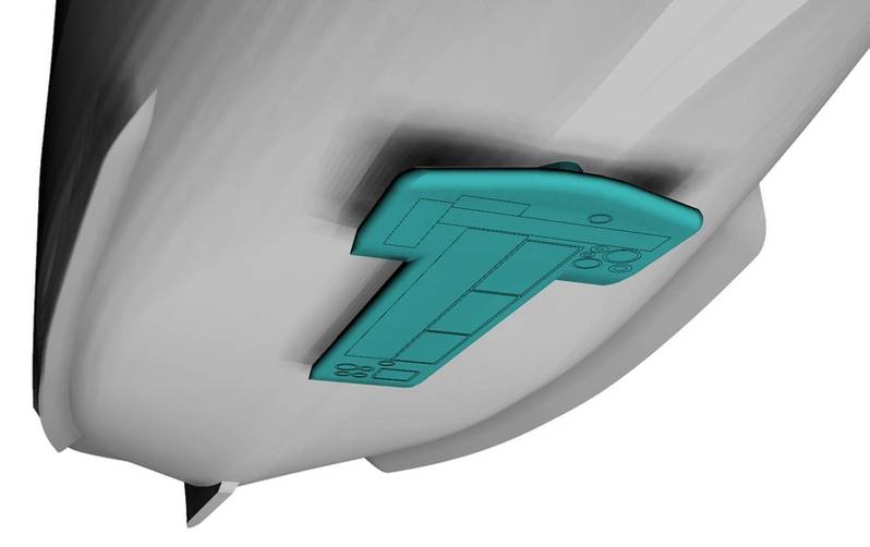 The new gondola, helping to place the scientific sensors a few feet beneath the hull and 'bubble wash.' Image courtesy Glosten
And some insights on the new power package?
CAT engines were chosen as the existing generators were CAT and SIO was familiar with the engines. Additionally, CAT was used on the Thompson repower, so there was the ability to learn from the previous installation as well as provide some commonality across the fleet. The configuration and size of the generators was determined in a Repower Study completed for the University of Washington for the Thompson midlife. The study compared capital and lifecycle cost, as well as reliability and adequate redundancy for a number of configuration options. The configurations included
- Replacing propulsion alternators
- New engines
- New gensets
- Integrated bus
- Integrated bus with new alternators
- Repower
- Repower with variable speed
The goal was to find the best value, including reduction in risk of failures impacting missions, lifecycle cost, and reduction in emissions. The chosen configuration of four generators, two large and two small, on an integrated bus provided the best overall reliability and fuel economy.
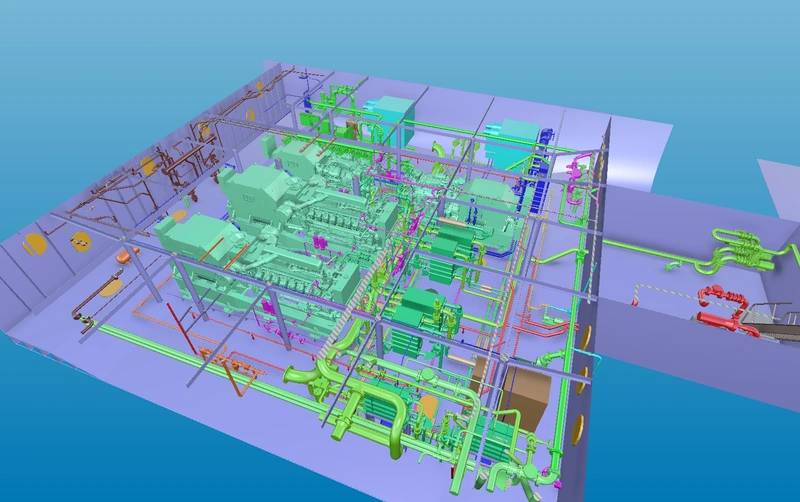 Cadmatic model of main engine room with new equipment. Image courtesy Glosten
Insights on the BWMS?
An Optimarin Ballast System (OBS) rated to 100 cu. m./hr. ballasting and 167 cu. m./hr. deballasting was chosen for the job. A study of available ballast water treatment systems was completed. It was found that, at the time, the Optimarin Ballast System was the only appropriately sized ballast water treatment system (BWTS) which was United States Coast Guard (USCG) type-approved. While others may have obtained approval by the time of construction, Glosten recommended to design around and install a USCG type-approved system to reduce project risk and ensure a path to approval.
Insights on the Bowthruster?
During the Thompson midlife, steel wastage was found in generally inspectable areas supporting the existing bow thruster. This steel repair was expensive and was something we wanted to avoid for the Revelle. One option was to assume the same steel repairs would be required. The other option was to avoid the complications for that repair by replacing the bow thruster. The replacement option was considered given the high noise levels in the forward and below deck staterooms when the existing bow thruster was above approximately 50% power – the primary noise source being cavitation.
To achieve the desired noise reduction, an azimuthing retractable bow thruster was considered. When performing dynamic positioning at sea, the bow thruster would be in the lowered position. This had two primary benefits. First, the azimuthing propeller would provide more effective power at the propeller and therefore require less power from the motor. More importantly, the propeller would be in better flow and could operate and high powers without cavitation. Additionally, once cavitation started, the noise is below the vessel and would have a less direct path to noise in the staterooms. When in shallow water, the thruster is retracted and acts as a tunnel thruster.
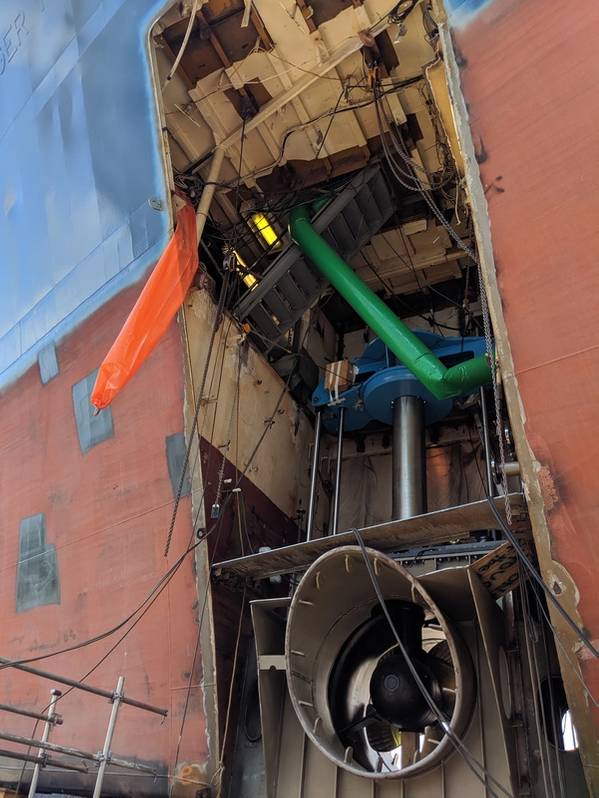 Installing the new retractable bow thruster from ZF Marine. Photo courtesy Glosten.