
Finite Element Solutions


For the Global Offshore Market
The international marine industry faces unprecedented challenges today. Energy costs are rising, as are concerns about reduced pollutant emissions, water ballast treatment and other environmental impacts. A tight credit market and cash-strapped operators mean that engineers must deliver designs with a high degree of fidelity and reliability while reducing the development cycle. Extreme weather, hazardous cargoes and other challenging operating conditions present the need to continually innovate, implement new materials and deliver analyses confidently.
How can naval architects overcome these challenges? One answer lies in leveraging the power of engineering simulation in an integrated environment with broad capabilities.
For more than 40 years, ANSYS’ robust capabilities allow engineers to conduct design analyses and optimization studies that reflect the most demanding environments – ultimately helping naval architects to design new hulls, appendages, sails, propellers, platforms, and other equipment.
By using finite element (FE) technology, engineers can quickly arrive at groundbreaking innovations without investing time and money in physical prototypes. Engineers can subject their designs to extreme temperatures, waves, wind loading, cargo weights and other real-world conditions to assess their response. Not only can engineers verify and introduce their ideas faster, but they can predict how their designs will perform under actual operating conditions. Engineering resources are amplified, as design teams these days rely on advanced numerical modeling to automate and streamline the design process.
Marine and offshore engineers face special challenges as their designs must withstand a range of operational, transient, accidental and dynamic loads.
Improved Support for Large Simulations
Geometrically modeling the complexities of an offshore structure is a numerically large and compound task. So naval architects often rely on high-performance computing (HPC) environments to conduct these simulations.
Improved performance for large models is a primary focus for ANSYS to reduce product development cycle times and lost productivity. The technology is designed to deliver maximum speed and efficiency across multiple computing processors. ANSYS customers have leveraged HPC environments and enhanced technologies to achieve significant reductions in their simulation runtimes, particularly when running distributed tasks across multiple processors. Fluid–structure interaction problems that rely on computational fluid dynamics (CFD) studies are now easier to set up, solve and post-process with ANSYS CFX and ANSYS Fluent. In ANSYS Workbench, popular CFD solution methods share a common workflow, where interaction with other products is enabled through controlled workflows. This reduces the learning curve for engineers who want to use both CFD technology and structural engineering solutions.
Customized Capabilities
While many technology enhancements benefit all ANSYS users, improving solvers targeted specifically at marine applications, including industry-leading solutions ANSYS Aqwa and ANSYS Asas, has been a top priority.
Both Aqwa and Asas have benefited from major changes in the last few years, with the intention to add even more capabilities in the future. Recent enhancements include more user-friendly modeling, the ability to import geometries from third-party CAD packages, trouble-free design parameterization, efficient load definition and the option to choose multiple wave theories.
In addition, ANSYS DesignXplorer offers improved capabilities for conducting optimization studies. A new direct optimization system can gather information via data links to other systems or components that contain design-point data. This new system supports earlier decision-making, decreasing overall development cycle and eliminating a lengthy trial-and-error period. Engineers can easily visualize the tradeoffs among design variables and make choices that support the desired output. Figure 1 demonstrates a number of design variables considered in the design of a jacket structure.
Design assessment in Workbench now includes code-checking capabilities with Beamcheck and Fatjack. Design Assessment supports code checking, fatigue analysis and post-processing of user-defined results. Post-processing speed has been significantly improved, decreasing from minutes to seconds. Results can now be obtained and presented in a single result object, based on multiple intervals, wave cases or spectra.
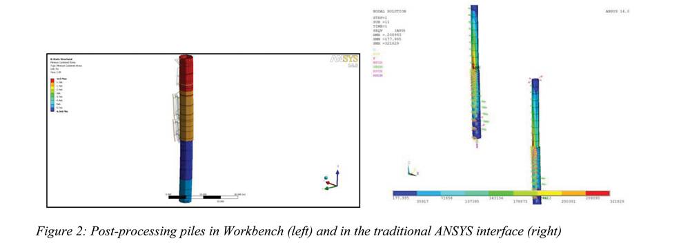
The powerful Splinter technology from Asas has migrated into Workbench to support simulation of soil–pile interaction of monopiles or pile groups. New built-in macros enable soil–pile interaction analysis via the use of command objects. The analysis can be solved in the traditional ANSYS interface if the engineer needs to take a close look at the piles themselves. Figure 2 shows a soil–pile interaction model post-processed in Workbench Mechanical (left), and in the traditional ANSYS interface (right).
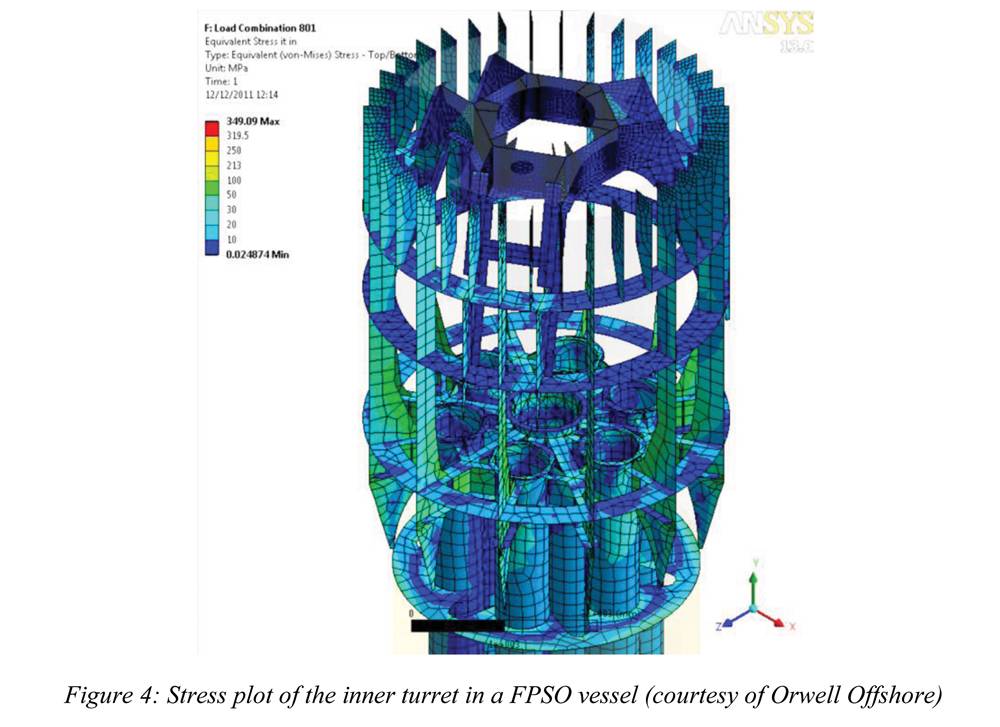
The recent addition of the intuitive Python programming language enables engineers to create user-defined graphical user interfaces (GUIs) in Workbench that support their pre- and post-processing needs. This technology can be accessed via the ANSYS Customization Toolkit (ACT), which supports a customized interface for interactive input, definition of restrictions and constraints, rapid validity checks, and decision-making support at the application level. For marine engineering studies, ANSYS Mechanical now includes built-in rotordynamics capabilities that reflect a more sophisticated way to study rotating machinery. The process for setting up analyses and applying loads has been streamlined and shortened. A GUI is used to define bearing properties and loads. When used with parameterization tools in DesignModeler, in conjunction with DesignXplorer, ANSYS solutions can shave time off the development process. ANSYS has served the marine industry for decades. The experience of thousands of global users has been incorporated into solutions specifically tailored for the marine industry. Figure 3 depicts the FE results of a decompression chamber in a 24-man saturation diving system onboard a dive support vessel. The design had to meet certain stress criteria from a pressure- vessel design code. In another application, Figure 4 shows a contour plot of stresses of the swivel and riser hang-off platforms housed in the inner turret system in a FPSO vessel. The design had to meet stress criteria against class rules.
Charting a Confident Course
A professional engineer’s world continues to change with ever-increasing demands for faster, larger, yet accurate FE solutions. Simulation technology can deliver answers from conception to decommissioning with integrity and performance. Few systems face the rigors of marine structures. With four decades of experience, ANSYS can confidently provide the tools to analyze your assets with a comprehensive range of technologies.
ANSYS is committed to making continuous improvements that reflect new engineering challenges. Whatever the future brings, ANSYS can help engineers chart a confident course toward market leadership.
About the Author
Spiro J. Pahos is a technical services engineer at the UK office of ANSYS, Inc., one of the world’s biggest CAE providers to the engineering industry. He received his M.Eng. and Ph.D. from the Universities of Glasgow & Strathclyde. Email: [email protected]
(As published in the October 2012 edition of Maritime Reporter - www.marinelink.com)