
UV-C Keeping Ship Hulls Free from Biofouling


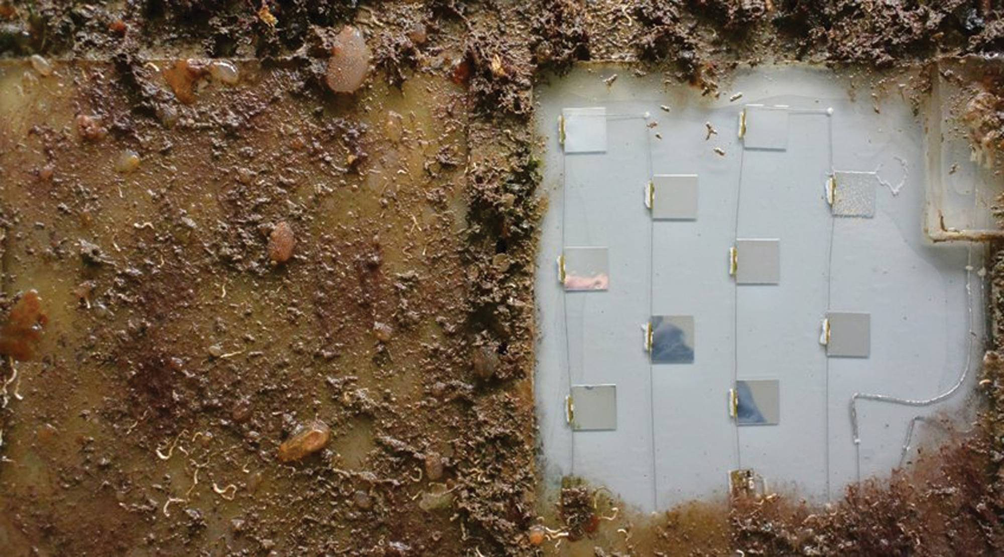
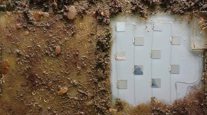 Figure 1: UV-C prototype kept clean from biofouling in the harbor of Melbourne (Australia). On the left a benchmark silicone panel is located without UV-C, which is completely bio-fouled (courtesy to Defence Science and Technology group for testing).
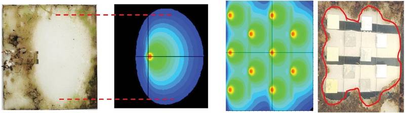 Figure 3: Comparison of model simulations of the UV irradiation at the surface with corresponding biofouling tests. On the left for a silicone slab with a single LED, tested in an aquarium. On the right for a full prototype panel tested in sea condition. The red lines mark locations with 0.3mW/m2 irradiance level predicted from simulation.

The presence of biofouling on the hull of a ship increases the drag from the water during sailing and thereby the fuel consumption, which results in increased CO2 emissions as well as increased costs for the ship owner. Paints applied to the underwater areas on the hull of ships therefore often contain biocides to hinder biofouling growth or possess non-stick properties, allowing a release of the fouling when the vessels pick up speed.
AkzoNobel is working with Royal Philips to develop a new technology that employs a completely different approach to traditional paints used in biofouling control on ship hulls. It uses an ultraviolet-C (UV-C) emitting layer applied on the underwater areas of the hull to keep the surface clean from fouling. The UV-C irradiation inactivates or kills microorganisms through absorption by their DNA, a property regularly applied in water and air purification systems, preventing the attachment and growth of biofouling.
This new approach has demonstrated a capability to keep the surface completely clean from any biofouling (Figure 1), a level of fouling prevention not offered by the current paint systems. This is the case both when the ship is sailing and when it is docked. Stationary prototype tiles have been tested around the world and have been shown capable to remain clean in various locations that are known to pose a high fouling challenge, like Singapore and the Great Barrier Reef in Australia. In addition to reducing CO2 emissions by offering unparalleled antifouling performance, the technology is a biocide-free and zero-VOC solution, which are other important sustainability objectives.
The UV-C is emitted from UV-LEDs, which are embedded in a silicone light-guide that helps in distributing the irradiation across the surface. Prototypes are currently tiles of 30x30cm2 with a thickness of 10mm, and they have a cable hardwired in for powering. To optimize the area kept clean by the individual LEDs, they are configured such that they emit sideways into the plane. A portion of the emitted light is guided along the surface by the light-guide, which can be demonstrated with an external green laser with its beam incident on the side of the panel (Figure 2).
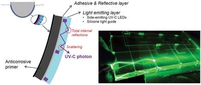 Figure 2: Schematic illustration of the working principle of the UV-C concept. On the right, the principle of waveguiding in a test panel is demonstrated. In the current design, reflective material is applied at the bottom to reflect the UV-C outwards, while some of it bounces back through total internal reflection at the silicone-water interface. Part of the UV-C being guided along the surface can exit the light emitting layer towards the outer surface through diffuse scattering, enabling UV-C exposure of the bio organisms at the whole surface.
Knowing the properties of the components, the materials used and the design of the tile allow a model simulation of the UV-C irradiance levels across the surface. By linking data from a single LED test sample with experimental fouling exposure observations, it was found that a low UV-C intensity of only about 1mW per m2 is found to be already sufficient to prevent biofouling (Figure 3 left panel). Subsequently, this threshold value can be used in model simulations towards designing a multiple LED containing light emitting layer, ensuring that positioning of the LEDs and other design parameters are such that the entire surface is being kept free of fouling (Figure 3, right panel).
Ultimately, on a ship, the technology will be applied under challenging in-service conditions. Additionally, components within the UV-C emitting layer may at certain locations be exposed to high UV-C irradiation levels. Material selection therefore becomes critical when having to take into account durability, processing and fabrication, as well as the overall design criteria associated with the technology. Despite these difficulties, a recent prototype has already shown to be still performing well after nearly two years of continuous operation in the field.
The bulk of the light guide is made up of silicone, which, when properly formulated, can exhibit a high UV-C transparency with a transmittance of about 80% per cm at 275nm wavelength. This property is critical for the performance of the technology, as it enables distribution of the UV-C across the surface to reach everywhere the relatively low intensity levels that keep the surface clean with the use of a limited number of LEDs. While being fairly flexible, aiding the application to curved surfaces, the silicone layer also protects the electronics embedded within. Mechanical testing of the prototypes has demonstrated that the electronics within the light guide can survive typical impact forces associated with water slamming or rubbing by fenders.
An adhesive backing will be used to fix the light emitting layer onto the hull of a ship. While currently, prototype designs are relatively thick (10mm), ultimately, designs would be closer to typical laminate films. Still, a careful selection of the adhesive solution is required. To this end, aside from laboratory testing, dedicated field testing is being done to assess the performance of the adhesives and ensure that the light-emitting layer stays in place.
New generation prototypes that are under development will have a thinner design (~4mm), with no hardwired cable, and provide a larger panel size (about 50x50 cm2). The format is enabled by newly available UV-C LEDs with a thin side-view package, which can be used directly for emitting in the plane without requiring the extra step of mounting the package sideways. Inductive coupling by placing the edge of a tile on top of a power strip will be used for powering the LEDs, omitting the need for a hardwired cable to connect each tile. Additionally, improvements in materials will be applied to avoid artefacts from stresses arising due to changes in material properties during processing.
Next steps in moving the technology towards the market will be developing a scalable fabrication, extending product lifetime, and the actual full-scale application on vessels. New prototypes will be tested on operational vessels as assemblies of tiles rather than with single tiles. This will help with allowing in-field installation procedures to be optimized, while the in-service use allows building a performance track record. With having achieved two years in-field performance, further improvement can certainly be expected. Gradually further improving the UV-C LED performance (lifetime, efficiency) will be the basis to come to future product solutions.
Combining capabilities from both companies, readying this technology for the market is now a global team effort. Where Royal Philips has expertise and intellectual property (IP) in designing systems using UV-LEDs, AkzoNobel has expertise in materials chemistry, adhesion and surface protection. Development of the system involves activities occurring in the U.S., Europe and Asia, and while ship hulls are the main application area that is targeted with the current efforts, possibilities for this technology also exist in niche area applications, such as sea chests. Overall, the technology offers unparalleled fouling prevention performance as well as benefits to sustainability targets, although a big challenge lies in getting it to work in the market, since it is so different from conventional solutions. Ultimately, collaboration and education are critical to making this novel and new technology a success in the marine industry.
The Authors:
Niek Hijnen (PhD) works in AkzoNobel’s coatings technology group, currently focusing on the technical development of the UV-C antifouling technology as well as new technologies for improving the anticorrosive performance of coatings. www.akzonobel.com
Michel Jongerius (PhD) has 37 years’ experience in Philips Research innovations in photonics and manufacturing technology. Currently, he is project manager of the RunWell project on UV anti-fouling