
NASA Welding Technologies Could Revolutionize Workboat Fabrication


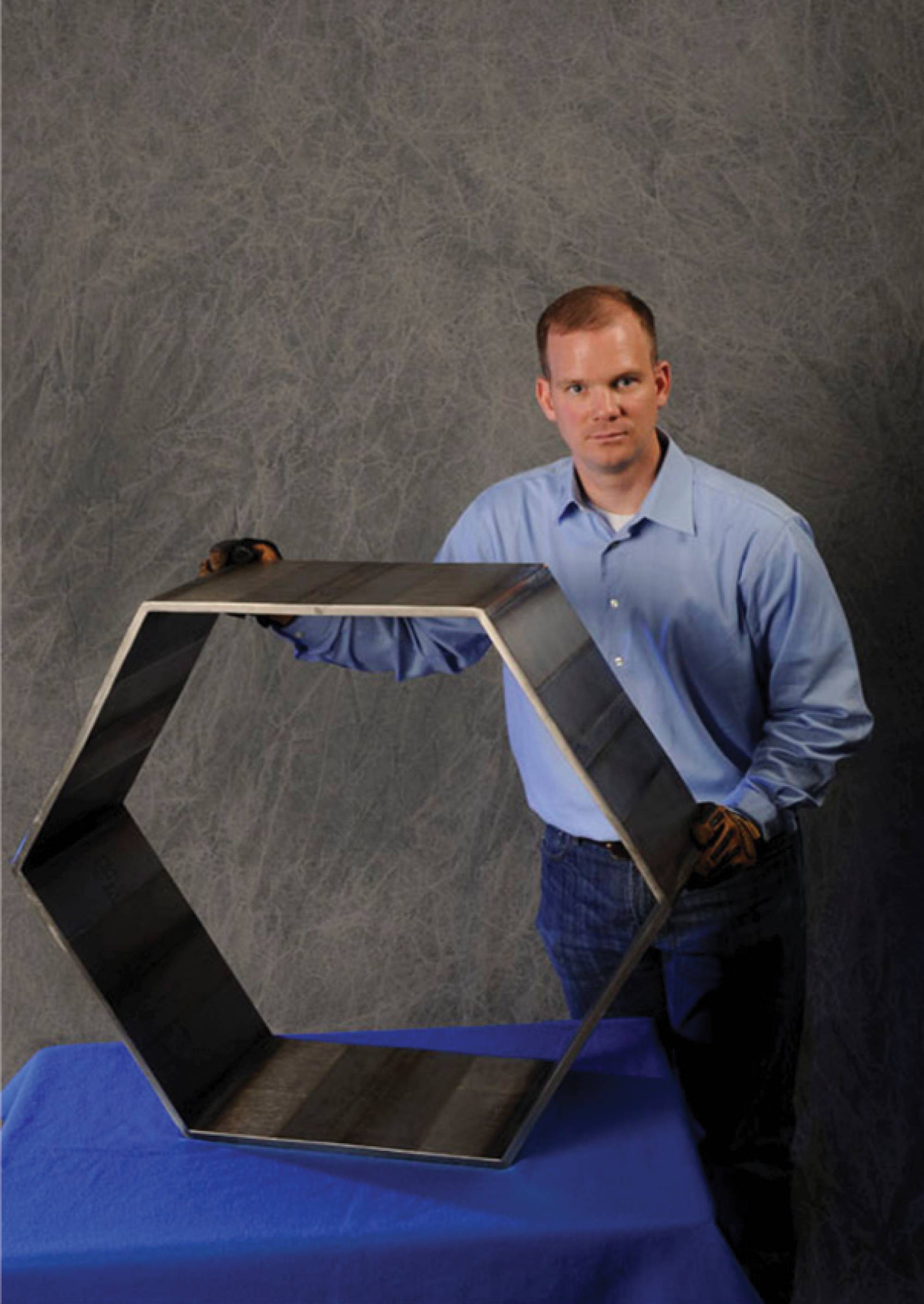
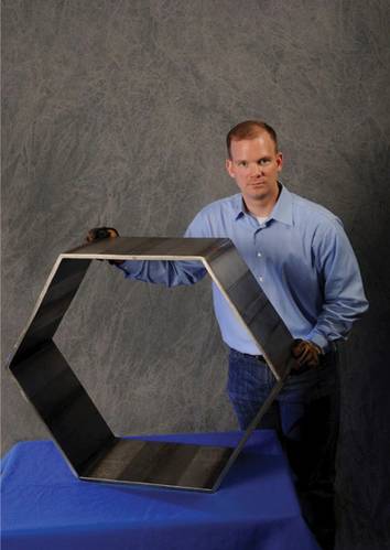 Figure 4. Hexaganal CP Ti structure showing angled TSW welds. Photo: NASA
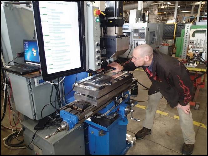 USW Prototype system at MSFC. Photo: NASA
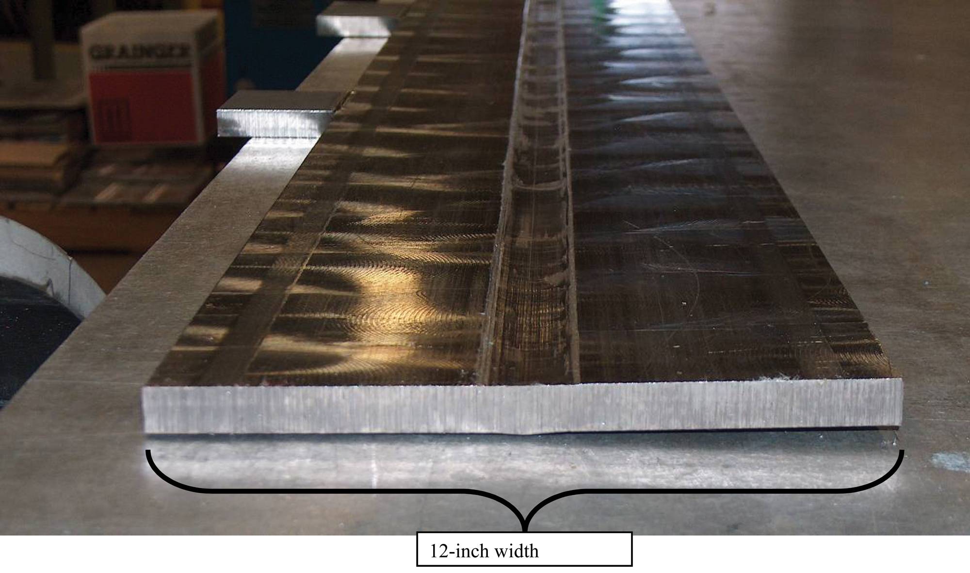
 Figure 3 Completed TSW of .5-in (12-mm) thick CP Titanium. Note the minimal thermal distortion. Image: NASA
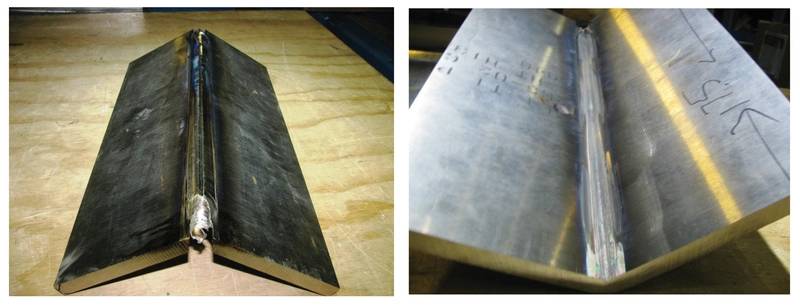 Figure 3 CP Ti .500-in thick angled weld outside and inside. Image: NASA


Solid-State Welding Processes Being Developed for NASA Manufacturing Programs Could Significantly Reduce Workboat Fabrication Costs
Whether it is for a tug boat, cargo vessel, or an offshore supply ship, much of the workboat fabrication industry is located along the Southern Coast of the U.S. But a visit to any one of the workboat facilities in that area (or any other in the country) would reveal antiquated and archaic fabrication processes used seventy years ago. The workboat manufacturing process is very expensive, labor intensive, and has not really changed since World War II. Perhaps it is time to go back to the drawing board and redesign the workboat manufacturing process from the ground up so that new solid-state welding processes and other aerospace technologies being developed at NASA’s Marshall Space Flight Center (MSFC) can be utilized to reduce costs and decrease manufacturing schedules. Although NASA welding development focuses on the aerospace discipline, many applications exist for these same solid-state weld processes in the maritime industry.
Solid-state welding technologies at NASA’s MSFC have made significant advances is support of NASA aerospace manufacturing applications. In addition to conventional friction stir welding (C-FSW) and self-reacting friction stir welding (SR-FSW), both of which are used in Space Launch System (SLS) cryotank manufacturing, MSFC is also developing the ultrasonic stir weld (USW) and the thermal stir weld (TSW) processes. These two processes are superior to FSW in that the heating, stirring, and forging elements are decoupled to allow independent control of each element. This allows for greater process control. The process advantages of all three solid state processes (FSW, USW, and TSW) result from the fact that the solid-state weld process takes place in the plastic phase below the melting point of the materials being joined. This precludes any possibility of solidification defects. The benefits include the ability to join materials that are difficult to fusion weld, for example 2XXX and 7XXX aluminum alloys, magnesium, and copper. Solid-state welding processes can use purpose-designed equipment or modified existing machine tool technology, and they are also suitable for automation and are adaptable for robot use.
Other advantages are as follows:
• Low distortion and shrinkage, even in long welds.
• Excellent mechanical properties in fatigue, tensile, and bend tests.
• Single pass welds.
• No arc or fumes.
• No porosity.
• No spatter.
• Ability to operate in all positions.
• Energy efficiency.
• One stir tool can typically be used for up to 1000 m (3280 ft) of weld length in 6XXX series aluminum alloys.
• No filler wire required.
• No gas shielding for welding aluminum.
• Some tolerance to imperfect weld preparations; thin oxide layers can be accepted.
• No grinding, brushing, or pickling required in mass production.
• Ability to weld aluminum and copper of >75 mm (3 inches) thickness in one pass.
• Once welding parameters are established, very, very few weld repairs required.1
Thermal Stir Welding
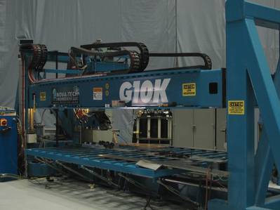 Figure 2 TSW Gantry Machine Used for Titanium Welding at MSFC. Image: NASABefore the introduction of the TSW process, it should be pointed out that FSW is a joining technology that is expanding in its application to space structures as a solid-state joining method with joint properties superior to fusion welding joints. FSW methods are primarily associated with high-strength aluminum alloys such as the Al-Li alloys used to manufacture cryogenic tanks, supporting structures, and rocket fuselage components. There is high interest in expanding FSW joining methods to higher-strength and higher-temperature alloys to include rocket engine components and other high-temperature materials applications for space. However high frictional forces and high stir welding temperatures make this a difficult challenge.
NASA has developed an innovative variation of the FSW process called Thermal Stir Welding (TSW), a process that introduces additional heat to the workpiece independent of the frictional heating between the stir tool and the metal. A description of the TSW process appears in Figure 1 and it shows the differences between the FSW and TSW processes. In FSW, the stirring RPM of the stir tool, the heating from the shoulder rubbing on the surface of the weld joint, and the compressive forging force from the shoulder cannot be decoupled. TSW decouples the three process elements and allows independent control of each. The stir tool RPM is independently controlled as well as the compressive forging loads from the upper and lower containment plates. The heating is independently controlled using an induction coil. Because of the independent control of the process elements/parameters, the real benefit of TSW is especially biased to thicker-section plate material and higher strength heat resistant alloys (i.e. titanium, steels, Inconels, etc.) where there is a mismatch between the stir parameters required to sustain frictional heating and the stir parameters desired for the hot working regimes of the alloy. Not to say that TSW’ing would not be beneficial for welding aluminum. It is capable of welding all aluminum alloys whether it is thin sheets or thicker sectioned aluminum, all in a single pass.
The development of the TSW process has led to the fabrication of a full-scale machine, shown in Figure 2. It was used to support previous work funded by the Defense Advanced Research Projects Agency (DARPA) and Office of Naval Research (ONR). Deliverables for this project was to successfully demonstrate the single pass joining of .500-in-thick (25.2-mm-thick) commercially pure (CP) titanium and Ti 6-4 ELI.
Since the TSW process de-couples the stirring, heating and forging functions of the FSW’ing process and allows independent control of each process element, novel and very unique applications/capabilities can be attained using the TSW process over the FSW process. Since the TSW process configuration uses non-rotating containment plates (instead of a rotating shoulder in the FSW process) to apply forging loads to the plasticized weld nugget, it is possible to form the upper and lower containments plates to a specific, unique geometry. This was done in the referenced work completed for DARPA/ONR. One of the deliverables was a hexagonally shaped structure which represented a sub-scale gun turret sub-component. Figure 3 shows one of the angled welds while Figure 4 shows the completed part. Note that the weld joint prep is a 60 degree angle and the stir tool travelled through the angled weld joint prep in a single pass. Another application for which the TSW process would be ideal is for the welding of lap joints.
Another advantage of the TSW process is the capability to weld using real time temperature control. This requires precise real time monitoring and control of the temperature in the weld zone. An example would be the welding of titanium where it is desirable to maintain the weld nugget temperature below the beta transus temperature of approximately 890C. (1634F). In order to maintain this weld nugget temperature, the proper induction coil temperature must be balanced with the deformational heating to assure the target temperature is reached and maintained during the entire joining process to produce a homogenous microstructure. In so doing, an input target temperature of 870C (1600F) is entered into the control system. The induction coil heats the weld workpiece to the input temperature, at which time, the workpiece moves between the upper and lower containment plates which clamp down on the workpiece with a desired forging force. The stir tool then begins stirring the weld joint. If the temperature sensor sees the weld nugget temperature fall below the input target temperature, the travel rate slows and/or the stir tool RPM increases and/or the induction coil power is increased. These three events, either independent or in tandem, will increase weld nugget temperature. If the input target temperature is exceeded, the travel rate will increase and/or the stir tool RPM will decrease and/or induction coil power will decrease all of which have a cooling effect on the weld nugget. One of the most important data points relative to excellent welds is knowing that a constant temperature is maintained during the weld with little fluctuation.
Ultrasonic Stir Welding
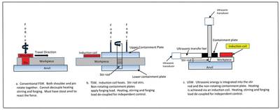
Figure 1 Schematic showing difference between FSW, TSW and USW. Image: NASA
USW is similar to TSW’ing in that the stirring RPM, heating, and compressional force of the containment plate have been de-coupled for greater process control. It is different than TSW and FSW in that ultrasonic energy is integrated into the rotating stir tool and the non-rotating containment plate. Figure 1 shows a schematic of the process and Figure 5 shows the USW prototype located at MSFC. The benefits of using the USW process include single pass welds in aluminum and heat resistant alloys, decreased plunge forces in the Z axis, decreased friction forces in the X axis, decreased shear forces in the X axis, increased travel rates, and increased stir tool life.
Isogrid and Orthogrid Structures
Manufacture of Space Launch System (SLS) rocket hardware, primarily cryogenic tank structures, takes advantage of the superior strength and rigidity found in Isogrid and Orthogrid structures. Figure 6 shows integrally stiffened Isogrid and Orthogrid structures. Both Isogrid and Orthogrid structures contain integrated stiffeners that characteristically have exceptional strength-to-weight or stiffness-to-weight ratios for many applications besides aerospace propellant tanks. Isogrid is able to withstand both compressive and bending loads, making it ideal for space and aerospace applications. Orthogrid has similar benefits to Isogrid, however it differs in terms of its structural pattern – the stiffening ribs use a square or rectangular waffle pattern rather than triangular. Both self-stiffened configurations are used where low weight, stiffness, strength and damage tolerance are important.
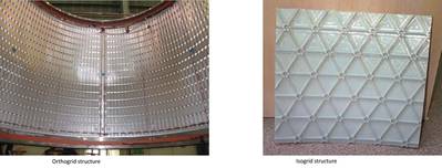 Figure 6: Orthogrid and Isogrid integrally stiffened structures. Image: NASAUsing NASA Technologies for Maritime Applications
Applying aerospace technologies to maritime applications would definitely be a challenge. A “bottoms-up” approach would have to be implemented beginning with stress and failure analysis which would lead to preliminary hull designs. New boat hull designs could focus on the elimination of hundreds of structural stiffeners, thus reducing labor and inspection costs significantly. The new designs would allow the use of new advanced solid state weld processes and materials; the same ones used in NASA’s space hardware manufacturing and R&D programs such as the Space Launch System Program. Cost benefit analysis and trade studies would lead to the break-even point for new technology infusion into the maritime industry. A manufacturing prototype demonstration article could be fabricated and tested showing the cost savings benefits of automated solid state single pass welds with far superior strength than manual fusion welds, as well as further cost savings and positive schedule impacts using automated real time weld inspection processes.
Recognizing advanced manufacturing processes and techniques are used and being developed for aerospace applications in the U.S. aerospace industry, perhaps the maritime industry sector should investigate the technologies outlined in this article as well as other advanced materials and processes available to modernize shipbuilding efforts. Possible pathways to modernization include consortiums, partnerships and other co-development arrangements that can focus on maritime manufacturing applications.
Due to limited space, this article has been abbreviated and touches on the highlights of technology used and developed for NASA manufacturing programs. For more detailed information, contact Mr. Sammy Nabors, Technology Transfer Program, Marshall Space Flight Center, 256-544-5226.
1 The FSW process was used in the External Tank Manufacturing Program in support of the Space Shuttle Program. FSW was used to complete longitudinal welds in the last six liquid hydrogen (LH) and liquid oxygen (LOX) tanks. The only known FSW defect occurred in manufacturing when the power went off half way into a twenty foot LH tank weld. After Material Review Board (MRB) disposition, it was decided to qualify a FSW repair technique, thus, preventing the scrapping of the liquid hydrogen tank
About the Author: Jeff Ding
Jeff Ding began his career at NASA’s Marshall Space Flight Center in June, 1986. His education includes a B.S. in Biology, Bowling Green State University 1976, B.S. Welding Engineering, The Ohio State University 1986, and a Masters in Science, University of Tennessee 1993. He brought the friction stir welding (FSW) process to the NASA agency in 1995/1996 time frame when he secured a 14 ton Kearney and Trecker Horizontal boring mill and converted it to NASA’s first FSW system. He completed his first FSW welds November 1996. He continued FSW development as well as ultrasonic stir weld (USW) and thermal stir weld (TSW) since 1996 and has authored 13 U.S. patents in solid state welding technology.