

Marine Biofouling in Ports: Wet Docks Acting as ‘Hot Spot’ Biofouling Transfer Stations


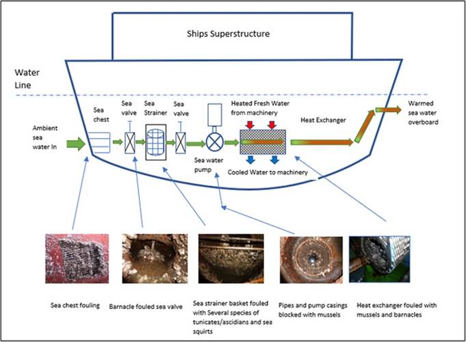 Figure 3. Ships Sea Water Cooling System Components. Source: The Author
 About the Author: During his original career as a Ship Master and Fleet Manager, Dave Smith observed first-hand the damage wreaked on the marine environment by the relaxed operational practices of the marine industry during the early 70s and 80s. On coming ashore to senior management positions and gaining a Master’s Degree in Safety and Environmental management, Dave developed an enduring desire to put right the ecological sins unwittingly committed by his previous maritime peers. To this end, h

The GEF-UNDP-IMO Glofouling partnership (2017) is a global initiative to counter the environmental issue of invasive aquatic species (IAS) and the resulting harmful ecological and financial damage that can occur when such invasion events are introduced through the medium of biofouling on ships hulls and other marine structures such as those found in the oil and gas industries.
One of the key objectives of the Glofouling project is to develop a Global Knowledge Hub and also identify areas where current information may be lacking but is relevant to the understanding of how IAS is transported via biofouling in ships at both local and international level.
One such knowledge gap is where enclosed wet docks (See Figure 1) may provide an enhanced haven and vector platform for IAS to relocate between ships at berths within the facility. The nature of such a transfer phenomenon is briefly described in this article along with some potential mitigation measures that vessels or ports may employ to reduce the perceived threat.
Vessels arriving in ports from other bioregions can introduce an extensive range of potentially invasive aquatic species via the medium of the accumulated biofouling carried on their hulls and other underwater appendages (miller et al, 2018).
To determine the level of this hazard posed by shipping in particular ports, there has been some work done to develop risk assessment methodologies which can be utilized to quantify the biosecurity danger; such as that described by the Australian Department of Agriculture, Fisheries and Forest (DAFF, 2011) which analyses the factors determining port inoculation events.
When considering the possibility of biofouling species transfers within a port, the local hydrodynamic environment has been identified as a factor which can magnify the intensity of fouling both on substrates such as the harbour structures and also on the hulls of vessels visiting the port. The influence of port features such as breakwaters, berthing arrangements and confined entrance channels all have an effect on tidal flushing and the potential consequent accumulation of viable propagules for biofouling transmission (Floerl and Inglis, 2003).
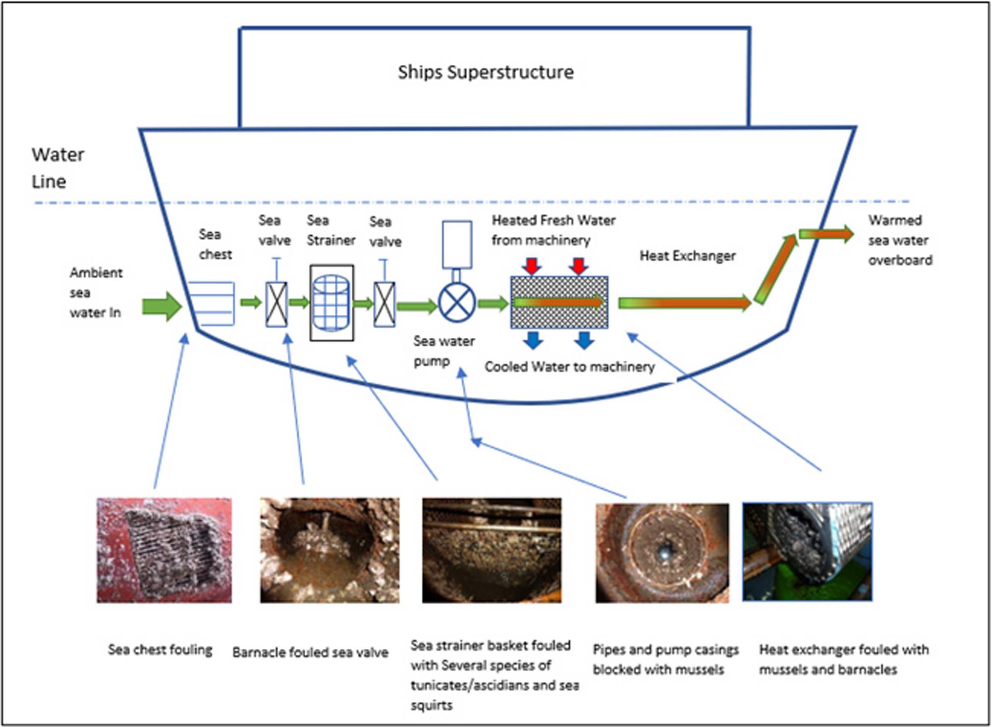
Wet Docks are port facilities where the water is enclosed and kept at a certain level to allow for the loading and unloading of ships. A representative wet dock arrangement is shown in figure 2. Such docks are often found upstream in rivers and allow for ship cargo operations to take place near hinterland industrial areas, regardless of tidal constraints. They provide sheltered conditions where a ship can remain afloat at all times. Ship access to the dock is via a lock system fitted with sealing gates and pumps to regulate the lock water level from the external tide height to that of the operational depth of the dock.
 Figure 2. Typical Wet Dock arrangement. Source: H Eustice
Once berthed within such a dock, conventional transfers of hull biofouling organisms may occur through the deposit into the dock water of detached biological material as a result of physical contact with Tugs and berth fenders or the spontaneous release of fertilized cells arising from other stimuli such as temperature and salinity changes (Minchin and Gollasch, 2003).
Due to the nature of water enclosure in a wet dock, it is suggested that this may represent a significant increase of biofouling risk as opposed to ports which are open to sea or river environments. There appears to be a lack of study concerning the biofouling transfer mechanisms within such enclosed port areas. An area of particular note is the possible effect of a ships cooling water system in these docks and the consequent potential for berthed ships to more rapidly exchange different biofouling species within the confines of the dock itself.
While hull surfaces are a commonly acknowledged transport pathway for biofouling and IAS, there have also been studies carried out to highlight the biofouling accrued by ships in their internal sea water cooling systems and the enhanced biosecurity risk that this may also represent (Growcott et al, 2016).
For ships, external sea or dock water is used as a cooling source for the main and auxiliary engines via an internal heat exchanger system (Jones and Little 1990).
A simplified schematic of a sea water cooling system and its principal components is shown in Figure 3.
For a ship berthed in a wet dock, incoming dock water at ambient temperature enters the cooling system via the sea chest and strainer. The sea water circulating pump creates a rapid flow of cooling water to the heat exchanger. The heat exchanger contains heated fresh water arriving in a closed circuit from the various items of machinery on board such as diesel engines, oil coolers and refrigeration plant. Dock water is passed through the exchanger in sealed tubes or plates and comes into contact with the surrounding heated fresh water circuit. The heat is transferred to the pumped dock water as it passes through the exchanger. The cooled fresh water is then returned to the machinery distribution arrangement whilst the heated dock water is passed overboard back to the dock again.
The cooling systems are often fitted with internal biofouling growth prevention measures but, as can be seen from the photos in Figure 3, they are not always effective in removing all the biofouling accumulation.
To realize the potential scale of the cooling water biofouling issue related to ships in wet docks, the temporal volumes of cooling water that ships can take up and discharge in the dock need to be considered:
With regard to larger vessels in the region of 200 metres in length (as represented in Figure 2), whilst the main engines would not be running in the dock, there could still be a considerable cooling water demand for extra generator power requirements associated with cargo handling etc. For the purpose of demonstration and subject to vessel type, an estimate for a vessel of this size in port could involve pumping through some 450 m3/hour of water from the dock into the internal cooling system and back out into the dock.
The total stored water capacity of the representative dock in Figure 2, with an operating depth of 15 meters, would be in the region of 5400,000 cubic metres of dock water. Thus, with 5 ships in the port exchanging a total of approximately 54,000 cubic metres of dock water in every twenty-four hours, around 10% of the total water available is being processed daily through the berthed ships cooling water systems. This represents a substantial quantity of circulated dock water, which has the potential to double every day that the vessels remain in port.
This mass rotation of shared dock water, with each vessel vacuuming up 450 m3 of dock water every hour, passing it over all the possibly fouled internal components of the cooling system, warming it up and then ejecting it back into the dock, as shown in Figure 2, may represent a considerably enhanced biosecurity risk. Once again, detachment of material or spawning events within the cooling system will increase the propagule pressure within the wet dock water mass.
Further to this, given that different species may have been brought into the dock by vessels from varying geographical regions, the enclosed dock and the circulating gyres of warmed dock water created by the berthed vessels cooling water pumps introduce the prospect of each vessel more rapidly sharing its biological load with others and departing the port having been duly seeded with additional species.
It is recognized that the use of the entrance lock facility may result in some exchange of dock water with the adjacent river estuary or coastal region as would water quality supervision through the use of pumps to exchange water or allowing ‘free flow’ of river water through the locks for limited periods when tidal constraints allow.
When considering the potential mitigation measures to reduce this latent risk of biofouling and hence IAS transfer when ships are berthed in Wet Docks, the following can be considered:
The biofouling of the internal components of a ship cooling water system has been traditionally addressed by the use of biocidal agents such as copper ions produced by electrically fed anodes in the sea chest as shown in Figure 4 or the direct injection of low concentrations of cleansing chemicals such as sodium hypochlorite either supplied to the ship in bulk drums or produced by electrolysis systems on board.
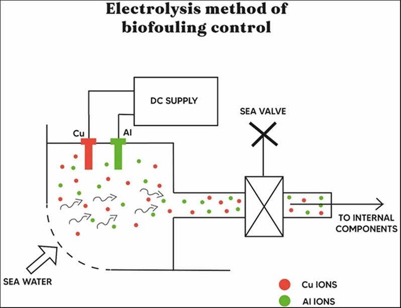 Figure 4. Typical Copper Anode arrangement fitted to a ship’s sea chest
A typical anode system will employ Copper ions for biofouling control and Aluminium ions for corrosion control. Whilst these methods can be successful if maintained correctly, they may have some deleterious effects by passing their low concentration toxic substances overboard into the receiving dock water, potentially affecting other untargeted organisms in the vicinity.
The undesired chemical side effects of these biocidal type systems and their questionable environmental standing has resulted in the development of more ecologically responsive solutions such as those employing the use of fitted transducers, as shown in Figure 5. These are designed to transmit Ultra Sonic Frequencies, creating non-inertial cavitation which is designed to destroy the biofouling organisms within the cooling system in a localized manner without the use of potentially harmful compounds.
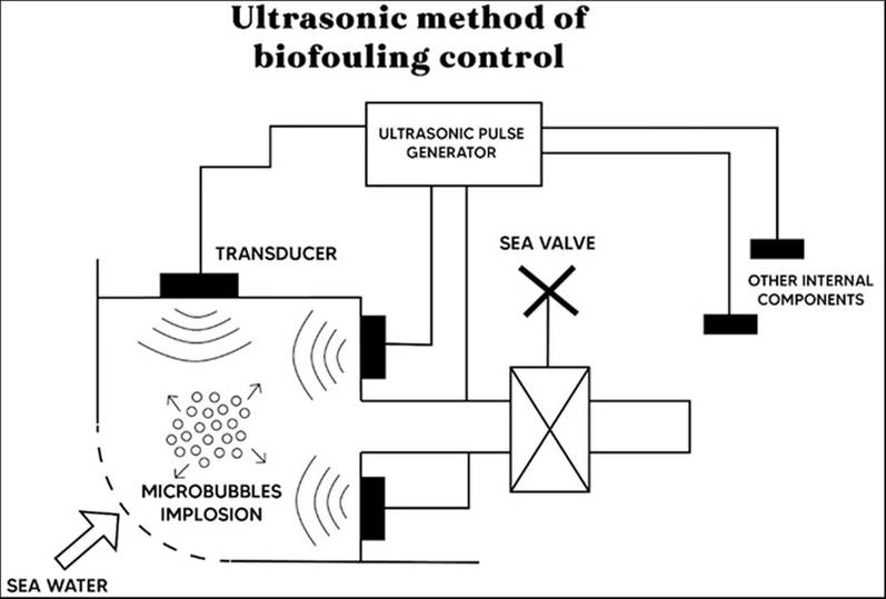 Figure 5 . Ultrasonic Transducer arrangement fitted to a ship’s sea chest
It is worthy to note that the use of this ultrasonic technology is not limited to sea water cooling systems and has been employed to counter marine biofouling in other areas of a ship such as on propellors and rudders
Given the large quantity of cooling water that is taken up and discharged by the cooling pumps fitted to a ship, it is often the case that the cooling water pump capacity may be set at a fixed rate to accommodate all the calculated heat exchange requirements when the vessel is at sea with her main engines and all other associated machinery running. When in a wet dock, it may be useful to be able to control the pump speed directly to reduce the throughput of cooling water rather than using a by-pass system to alter the water flow to the heat exchanger. Investigative work by Theotokas (2017) showed that the use of variable speed pumps (VSP) for the cooling systems could not only reduce the annual power consumption of a ship but also increase system performance by closer control of key temperature parameters. Another advantage of using VSP in this case would be the reduced volume of water being circulated between ships in a wet dock and hence a lower risk of IAS spread within the dock.
Possibly the most effective measure to combat the movement of IAS within a wet dock and indeed at any port facility would be not to use the ships machinery to generate electrical power when at a berth but instead use a shore electrical supply. This technology is termed ‘Cold Ironing’ and was first introduced several years ago as a measure to reduce Greenhouse Gas Emissions by ships in port. By effectively removing the demand for generated power, the need for significant quantities of cooling water is also removed and the cooling water pumps may be stopped altogether subject to vessel design. This would significantly reduce the risk of IAS transfer from the cooling water system. This technology is now available in several North America and European Ports and is growing in use.
It is noted that wet docks offering communal berths for ships have a clear potential to act as ‘hot spots’ for the transfer of biofouling species. A more detailed understanding of the complexity of wet dock biological mechanisms, with a particular reference to the influence of ship processes, could assist with more effective port environmental management, reduce the risk of IAS transmission and assist with the compliance with other regulatory demands such as water quality directives.
References
- DAFF – Australian Dept. of Agriculture, Fisheries and Forest. (201 ‘Species Biofouling Risk Assessment’. Available at: https://www.agriculture.gov.au/sites/default/files/sitecollectiondocuments/animal-plant/pests-diseases/marine-pests/biofouling-consult/species-biofouling-risk-assessment.doc
- Floerl,O and Inglis,J. (2003) – ‘Boat Harbour design can exacerbate hull fouling’. Austral Ecology 28(2):116-127. Available at: Boat harbour design can exacerbate hull fouling - Floerl - 2003 - Austral Ecology - Wiley Online Library
- Glofouling Partnership Project (2017) – available at: GloFouling Partnerships Project (imo.org)
- Growcott A, Kluza D, Georgiades E. (2016) Literature review: In-water systems to remove or treat biofouling in vessel sea chests and internal pipework. MPI Tech paper No. 2016-16. Nz. Govt.
- Jones JM, Little B (1990). USS Princeton (CG 59): impact of marine macrofouling (mussels and hydroids) on failure/corrosion problems in seawater piping systems. Naval Oceanographic and Atmospheric Research Laboratory, USA. 19 pp.
- Miller, A.W., Davidson, I.C., Minton, M.S. et al. (2018) Evaluation of wetted surface area of commercial ships as biofouling habitat flux to the United States. Biol Invasions 20, 1977–1990 (2018). https://doi.org/10.1007/s10530-018-1672-9
- Minchin,D & Gollasch, S (2003) Fouling and Ships' Hulls: How Changing Circumstances and Spawning Events may Result in the Spread of Exotic Species, Biofouling, 19:sup1, 111-122, DOI: 10.1080/0892701021000057891
- Theotokatos, G., Sfakianakis, K. & Vassalos, D. Investigation of ship cooling system operation for improving energy efficiency. J Mar Sci Technol 22, 38–50 (2017).Available at: https://doi.org/10.1007/s00773-016-0395-9


![Photo of MT Andaman, [IMO number 9807968] a 30m Indian Navy tug. Converted in 2024 for full uncrewed, remote piloting operation approved by the Indian Register of Shipping.
Image courtesy MDL.](https://images.marinelink.com/images/maritime/w100h100c/photo-of-mt-andaman-imo-170467.jpg)