

Designing the New National Security Multi-Mission Vessel


 (Image: Herbert Engineering / MARAD)
 (Image: Herbert Engineering / MARAD)
 (Image: Herbert Engineering / MARAD)
 (Image: Herbert Engineering / MARAD)
For more than 100 years the U.S. has depended on State Maritime Academies (SMA) to produce USCG licensed merchant officers. The SMA’s have also been an important source of U.S. Navy and U.S. Coast Guard officers, as well as trained personnel for the maritime industry and electric power industries ashore. Key to training these future deck officers and engineers has been the annual sea cruise on dedicated training vessels.
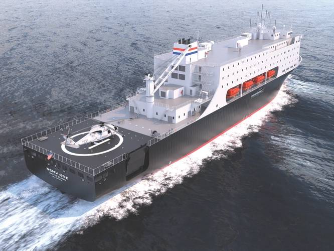
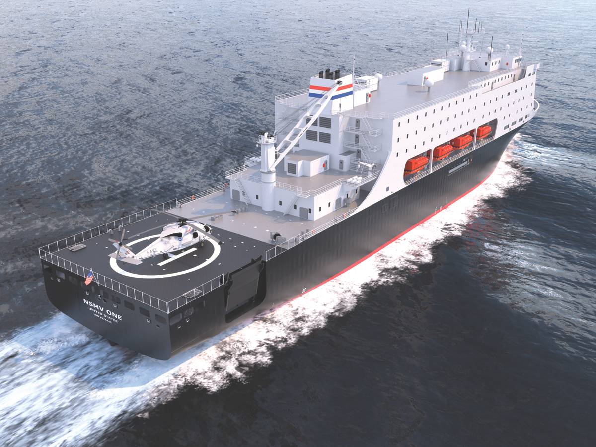
The current SMA training ships, all of which were built for other purposes and later converted to be training ships, are getting old. The oldest one, Empire State VI at New York Maritime College, was originally built as a cargo ship in the early 1960’s and has outdated steam propulsion. The newest training ships, at Cal Maritime and Maine Maritime, will soon be 30 years old. Much of the equipment on these ships is obsolete and vastly different from equipment on ships being built today. The U.S. Maritime Administration (MARAD) owns and funds the training ships and has embarked on a program to design and, it is hoped by many in the maritime industry, to build replacement training ships able to offer training with modern propulsion systems and navigation equipment, while also outfitted with improved berthing and equipped with flexible and fully wired class rooms, workshops and laboratories. Because the vessels are at the pier much of the year and they are U.S. government owned and managed, they can also be useful assets for government response to humanitarian and disaster crises in coastal and port areas. This ability to merge two primary missions into one vessel is a critical design feature that MARAD is looking to incorporate in the new training ships and is the reason for the class name given to them, the National Security Multi-Mission Vessel (NSMV).
Initial Design
Herbert Engineering Corp (HEC) was contracted by MARAD to prepare the NSMV design, and in 2015 a concept level design was prepared, with the Phase 3 design completed in early 2017, delivering a package that is expected to be sufficient for shipyards to prepare bids to build NSMV as the project progresses. It is hoped the new vessels will be delivered to all five SMA’s over time, starting first with the Academies with the oldest training ships.
Development of Requirements and Application to the Design
HEC and MARAD undertook a major effort to determine what features and capabilities to include in the NSMV design to best incorporate the wish lists of each SMA as well as the mission requirements for humanitarian relief and disaster relief (HA/DR). This has been an ongoing process for the two groups, working in consultation with the SMA’s and relevant parts of the U.S. government. There have been several rounds of design review and comment by the interested groups.
To start, MARAD in consultation with the SMA’s developed a list of unified requirements. The HEC design team then visited three of the training ships – at Cal Maritime, Mass Maritime and NY Maritime – to see how the training ships worked and to hear from the schools themselves what they wanted to see in the new training ships and equally important, what should be avoided. Fulfilling the requirements to be both a training ship and a HA/DR ship required a lot of design decisions and tradeoffs. Some of the key design features include:
- SAFETY: It was decided jointly by HEC and MARAD that the ships should be fully compliant with safety regulations and requirements for a ship carrying up to 760 persons, both international regulations and U.S. Coast Guard regulations and ABS Class Rules. This was a goal of the design even though as a U.S. government owned vessel documented as a Public Nautical School Ship, there was no legal requirement to meet SOLAS.
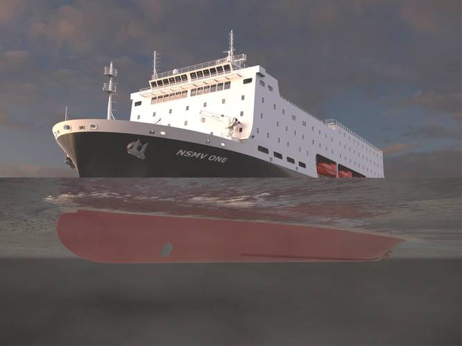
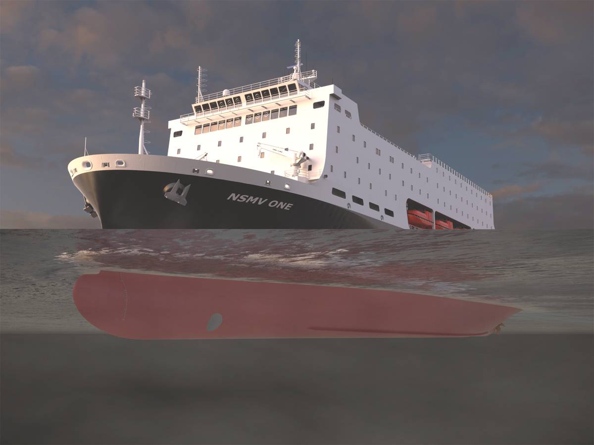
- SIZE: A key design constraint was that the ships fit within the pier length and draft restrictions at the five SMAs and operate at no more than 25 ft draft for access to smaller and less developed ports in support of HA/DR missions.
- LEAN & GREEN: Another design goal was for the ships to be efficient and economical to operate and also environmentally friendly. This goal is met by incorporating features such as full time operation on clean burning, low sulfur fuel, use of engine waste heat for accommodation heating, efficient LED lighting, and hull lines optimization for low propulsion power. LNG fuel was not adopted because the vessel’s intermittent operation made managing LNG fuel onboard difficult and the lack of regular routes makes it impossible to ensure a reliable supply of LNG. The hull lines optimization by CFD methods and model testing, carried out by model basin SSPA in Sweden, was effective in reducing required propulsion power by about 10% between the concept design and the optimized hull design.
- FORM & FUNCTION: A lot of the arrangement design was driven by the design goal to have a coherent and interconnected training ship environment while still providing practical and useful HA/DR mission capability. Meeting diverse requirements required focus on meeting key priorities and finding ways to integrate requirements into the same spaces. Some of the ways this was accomplished are as follows:
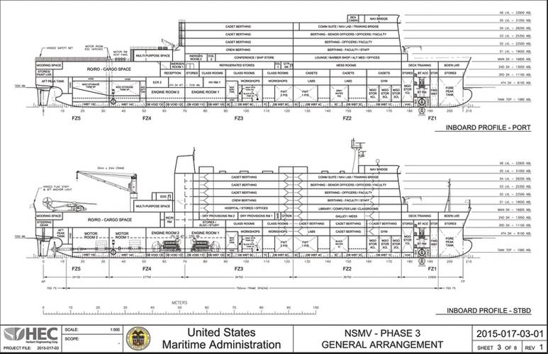
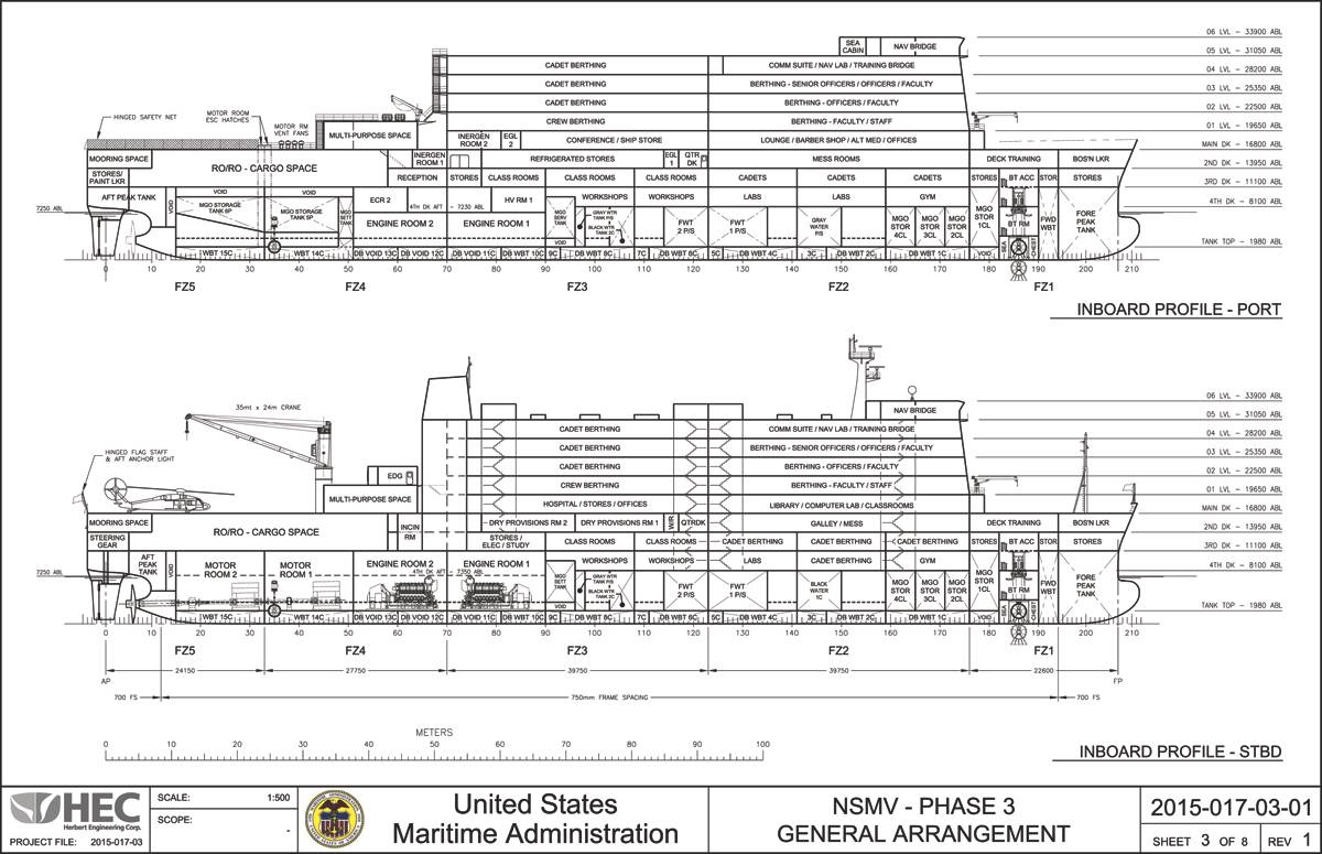
a. While HA/DR mission requirements are important to the design, they should not overly interfere with training ship capability. This was accomplished by focusing the HA/DR cargo carriage in the after part of the vessel and having the training ship spaces centered in the middle part of the ship to allow quick and easy access between all spaces. In this way berthing spaces are kept convenient to the mess, class and training facilities.
b. Berthing is provided for 700 persons in normal training ship mode, with 600 cadets and 100 non-cadets. An important quality of life feature and to make it easier to recruit persons to serve on the vessels, all 100 non-cadets have private cabins with private toilet and shower facilities. The goal was also to reduce the number of large cadet berthing areas compared to the existing ships. This is achieved by berthing 384 cadets in the accommodation deckhouse in four-person cabins, each with a separate toilet and shower unit. The remaining 216 cadets are in the typical 3 high berths located in the hull, but these spaces are convenient to class rooms and mess areas. During HA/DR missions, it was identified that there may be a need to increase persons onboard by 60 to a total of 760. This requirement is met by installing two high berths in some of the non-cadet cabins, so while these normally accommodate one person, in surge periods they can accommodate two persons.
c. The food storage, food preparation, food service, and mess areas are on the same deck and arranged for catering and service efficiency. This was an important requirement from the SMA’s.
d. Redundancy is provided as required by safety regulations and to continue essential services in case of a fire or flooding casualty in any one area. Safe return to port is possible even in case of loss of the main propulsion system, up to and including the main shaft and propeller. This is achieved by use of a drop down azimuthing bow thruster that can propel the ship at speeds over six knots.
e. Two separate engine rooms are provided for reasons of redundancy in an emergency and to allow training to take place in one engine room while the second is used for propulsion. This is feasible on training cruises because the ships generally operate at slower speeds, around 12 knots, since the purpose is to be at sea and not to quickly reach a port.
f. Required training spaces are incorporated into the design, including eight class rooms, navigation lab, computer lab, several cadet workshops, simulator spaces and other laboratory spaces. A separate training bridge is located one deck below the main bridge with full visibility forward and equipped similarly to the main bridge so cadets can experience navigation of the vessel without interfering with actual safe navigation.
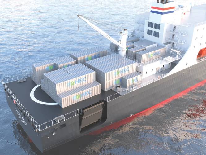
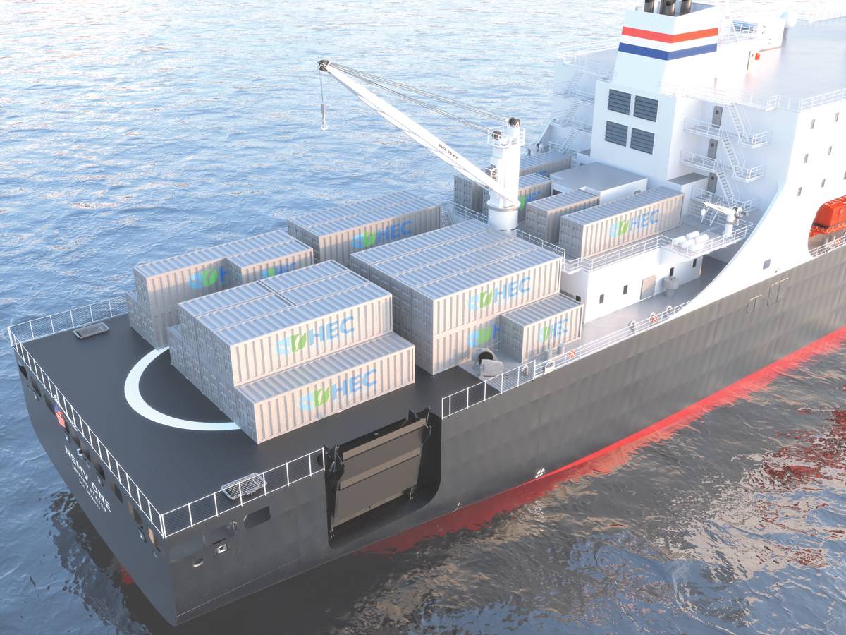
g. HA/DR mission capability includes transport of general cargo, containers, vehicles and trailers on the aft open deck area and in the enclosed RoRo space below that. A cargo crane, also useful for training, and a RoRo side ramp are provided to make the vessel self-unloading. Larger medical facilities than required for a training ship are provided and these can be easily expanded, including loading of medical modules on deck and in RoRo spaces with utility hookups provided. Ability to land helicopters, a key HA/DR mission requirement, was met by making the open aft deck also a helicopter landing area, but without capability to refuel or maintain helicopters.
h. During HA/DR missions, it is necessary to keep key personnel berthing and command and control areas secure. This was accomplished by placing these areas in the forward half of the deckhouse and allowing this area to be kept secure by locked doors.
i. The vessel is able to maneuver and moor without tugs, considered useful for HA/DR missions when ports may be disrupted by a crisis, and this capability reduces vessel operating costs during normal cruises.
- TOPSIDE: The need for open deck cargo space and a RoRo deck led to several challenges. It was determined that placing them aft would result in the least interference with the primary training ship mission, however, this created a structural challenge with locating the large side ramp opening. It was desired to have a more forward ramp location so when it was in the up position it would not interfere with helicopter landing, but the full ship and fine mesh finite element analyses (FEA) carried out identified high stresses if this were done. The solution was to relocate the ramp aft and install a folding ramp with a low profile in stowed position, minimizing its interference with helicopter landing. The transition of the large deckhouse to the open main deck aft also created structural challenges that were identified using the FEA. Modifications to reduce stress concentrations included fitting large transition brackets at the aft end of the house and separating the multi-purpose space house, located aft of the deck house, from the main deckhouse and engine casing to free the connection from hull bending stresses.
Propulsion System
One of the key items to be resolved during the design was the propulsion system to be used. Normal today in passenger ships is the use of diesel electric power, useful because of the large ship service electric loads to service the large number of persons onboard and because the engines can be put on line or taken off line to suit a wide range of operating speeds. These same requirements applied to NSMV so the initial decision was made to adopt an integrated electric drive propulsion system, similar to cruise ships worldwide. The simplest and most common prime mover for the electric generators are medium speed diesel engines. These offer low initial cost, relatively small size, and good fuel efficiency. These advantages made them attractive to both MARAD and HEC and thus the decision was made to use diesel electric propulsion on NSMV. This met with some resistance from the SMAs, who are looking at the training aspects of the vessel as well as efficient operation. However, it was felt that alternative propulsion methods such as steam turbines, gas turbines, or low speed diesels would significantly increase the cost for construction, and in some cases significantly raise fuel consumption. Furthermore, low speed diesel is not well suited for electric drive, and it was believed training was available on these alternate propulsion systems using simulators or shore side installations.
NSMV Design Team
Herbert Engineering collaborated with several other companies to provide the full range of design capability needed for a full ship design.
Key contributors were as follows:
- Herbert Engineering was the project lead and lead on arrangement, structure, systems, machinery, stability, and regulatory compliance design. Assistance was received from Carl Setterstrom, consultant naval architect.
- Jamestown Metal for galley and mess design and training space and cabin layout.
- SPAR Associates for cost estimation.
- SSPA, Sweden, for hull lines optimization, model testing and propeller design
- VT Group for IT infrastructure design
- B. Rosenblatt & Associates for accommodation piping systems and machinery space arrangements.
DESIGN PARTICULARS
Length o.a.: 159.85 m (524.5 ft.)
Beam: 27 m (88.6 ft.)
Draft: 6.5 m (21.4 ft.)
Design service speed: 8 knots/15% sea margin
Cruising Speed: 12 knots
Propulsion: Diesel Electric
Propulsion engines: 4 x Diesel Generators
Total installed Power: 15,680 kW
Propellers: 1 propeller, fixed pitch
Rudders: 1 flap type rudder on centerline
Fuel: Single fuel - marine gas oil (MGO), max Sulfur content 0.1%
Bow Thruster: retractable combi type - tunnel thruster in up position, azimuthing thruster in down position, “Take Home” source of power, 1450 kW
Bow Thruster: retractable combi type - tunnel thruster in up position, azimuthing thruster in down position, “Take Home” source of power, 1450 kW
Stern Thruster: Tunnel type, 890 kW
Fuel Consumption: 60 tons/day @ 18 knots, 26 tons/day at 12 knots
Fresh Water (including sanitary water): 35 gal/day per person for 700 = 93 tons + 5 tons Ship Service FW = 98 tons/day
Fuel range: About 11,000 nm range @ 18 knots design speed with 10% remaining fuel
Food & Stores: 60 days food storage for 700 persons, 297 sq. m. (3,200 sq. ft.) reefer provisions, 240 sq. m. (2,580 sq. ft.) dry provisions
Propulsion motors: 2 x 4,500 kW propulsion motors. Motors in separate watertight compartments.
Electric Power: 6,600 V main power generation, 440 V ship service electric power, 120 V lighting and accommodations
RoRo deck: RoRo space aft with length of about 40 m (130 ft), width inside framing of 24 m (80 ft), clear height of at least 4.7 m (15.3 ft). Usable deck area is about 1,000 sq. m. (10,700 sq. ft.). Suitable for about 10 x 40 ft trailers with 26 autos or about 49 autos/light trucks.
Total container capacity: about 64 TEU for two high.
Crane: 1 x Jib Boom type with 35 MT SWL x 24 m outreach
RoRo ramp: 20 ft. wide watertight wide side ramp with 40 ton capacity
Thae Author
Eugene van Rynbach is Vice President, Herbert Engineering Corp.
(As published in the August 2017 edition of Maritime Reporter & Engineering News)


